Crankshaft Assembly
1. On the
Home tab, click
 New
New from the
Data group. The
New dialog box opens.
a. Under Type click Assembly.
b. In the File name box, type crankshaft_assembly.
c. Clear the Use default template check box.
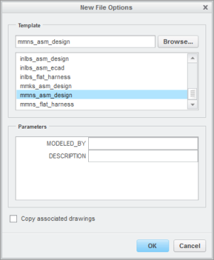
d. Click OK. The New File Options dialog box opens.
2. In the New File Options dialog box, do the following:
a. Under Template, select mmns_asm_design.
b. Click OK.
3. On the in-graphics toolbar, click

Datum Display Filters and make sure that all the datum display check boxes are selected.
4. If you do not see the datum labels, on the
View tab click
 Plane Tag Display
 and
 Axis Tag Display
 from the
Show group.
5. In the Model Tree, click

Settings, and then click

Tree Filters. The
Model Tree Items dialog box opens.
6. Click Features and click OK.
7. Select datum plane ASM_RIGHT in the graphics window.
8. On the
Model tab click
 Plane
Plane from the
Datum group. The
Datum Plane dialog box opens.
a. In the Translation box, type 32.65.
b. Click OK. A new datum plane ADTM1 is created.
9. In the Model Tree, select datum plane ADTM1, right-click, and click
 Pattern
. The
Pattern tab opens.
10. Click the arrow next to Dimension and click Direction.
11. In the Model Tree select datum plane ASM_RIGHT.
12. Double-click the dimension in the graphics window and edit the value to 89.3.
13. On the Pattern tab edit the number of members from 2 to 6.
14. Click

. The pattern of planes appears.
15. Click an empty place in the graphics window to deselect all items.
16. On the
Model tab, click
 Axis
Axis from the
Datum group. The
Datum Axis dialog box opens.
a. Hold down the CTRL key, and select datum planes ASM_FRONT and ASM_TOP from the Model Tree.
b. Click the Properties tab, and type CRANKSHAFT in the Name box.
c. Click OK.
17. In the Model Tree, expand Pattern1 of ADTM1.
18. On the
Model tab, click
Axis from the
Datum group. The
Datum Axis dialog box opens.
a. Hold down the CTRL key, and select datum planes ASM_FRONT and ADTM1 in the Model Tree.
b. Click OK.
19. In the Model Tree, select datum axis AA_1, right-click, and click
Pattern. The
Pattern tab opens.
20. Click
. A pattern of axes appears.
21. On the
Model tab, click
 Assemble
 from the
Component group. The
Open dialog box opens.
22. Select crankshaft.prt and click Open. The part opens in the graphics window and the Component Placement tab opens.
The crankshaft requires two assembly constraints. The first constraint aligns the assembly axis and the crankshaft axis. The second constraint positions the crankshaft along the axis.
23. Set the first constraint to align the assembly axis and the crankshaft axis:
a. Click the arrow next to
User Defined and click
 Pin
Pin.
b. In the Model Tree, select datum axis CRANKSHAFT.
c. In the Model Tree, expand CRANKSHAFT.PRT and select datum axis SHAFT.
24. Set the translation to position the crankshaft along the axis:
a. Select datum plane ASM_RIGHT.
b. Select the planar surface on the CRANKSHAFT.PRT as shown in the following figure.
c. Right-click in the graphics window and click Flip Constraint.
25. On the
Component Placement tab click
.
26. On the
Model tab, click
Assemble from the
Component group. The
Open dialog box opens.
27. Select piston_assembly.asm and click Open. The part opens in the graphics window and the Component Placement tab opens.
28. On the in-graphics toolbar, click

Saved Orientations and click
 Front
Front.
29. Use the 3D dragger to move the PISTON_ASSEMBLY.PRT to the position shown in the following figure:
The piston requires two assembly constraints. The first is an axis constraint, which will allow the piston to slide along the assembly axis. The second constraint will fix the rotation of the piston.
30. Set the first constraint to allow the piston to slide along the assembly axis:
a. Click the arrow next to
User Defined and click
 Slider
.
b. In the Model Tree, expand Pattern2 of AA_1, and select datum axis AA_1.
c. In the Model Tree, expand PISTON_ASSEMBLY.ASM, and select datum axis PISTON.
31. Set the rotation of the piston:
a. In the Model Tree, select datum plane ASM_RIGHT under PISTON_ASSEMBLY.ASM.
b. In the Model Tree, select datum plane ADTM1 under Pattern 1 of ADTM1.
32. On the
Component Placement tab click
.
33. In the Model Tree, select PISTON_ASSEMBLY.ASM.
34. On the
Model tab, click
 Repeat
 from the
Component group. The
Repeat Component dialog box opens.
35. Select both references listed under Variable assembly references and click Add.
36. In the graphics window, select datum axis AA_2 followed by datum plane ADTM2.
Notice a second piston assembly is assembled
37. In the graphics window, select the following pairs of references:
◦ Datum axis AA_3 followed by datum plane ADTM3
◦ Datum axis AA_4 followed by datum plane ADTM4
◦ Datum axis AA_5 followed by datum plane ADTM5
◦ Datum axis AA_6 followed by datum plane ADTM6.
38. In the Repeat Component dialog box click OK.
39. On the in-graphics toolbar, click
Datum Display Filters and clear the
 Axis Display
,
 Point Display
, and
 Csys Display
 check boxes.
40. On the in-graphics toolbar, click
Saved Orientations and click
Default Orientation.
41. On the
Model tab, click
Assemble from the
Component group. The
Open dialog box opens.
42. Select connecting_rod_assembly.asm and click Open. The part opens in the graphics window and the Component Placement tab opens.
43. Use the 3D dragger to move and rotate the connecting rod assembly to the position shown in the following figure.
44. Set the constraint.
a. Click the arrow next to
User Defined and click
Pin.
b. Select the outer cylindrical surface of the connecting rod.
c. Select the inner cylindrical surface of the hole on the piston.
45. Set the translation.
a. Expand the first PISTON_ASSEMBLY.ASM in the Model Tree and select datum plane ASM_RIGHT.
b. Expand CONNECTING_ROD_ASSEMBLY in the Model Tree and select datum plane ASM_FRONT.
c. If needed, rotate the connecting rod assembly to expose the inner surface of the connecting rod.
46. Right-click in the graphics window and click Add Set.
47. On the
Component Placement tab, change
Pin to
 Cylinder
.
48. Select the outer cylindrical surface of the crankshaft.
49. Select the inner cylindrical surface of the hole on the connecting rod.
50. On the
Component Placement tab click
.
51. In the Model Tree, select CONNECTING_ROD_ASSEMBLY.ASM
52. On the
Model tab, click
Repeat from the
Component group. The
Repeat Component dialog box opens.
53. Select all the references listed under Variable assembly references and click Add.
54. In the graphics window, select the inner cylindrical surface of the hole on the second piston and the datum plane ASM_RIGHT.
55. Select the outer cylindrical surface of the second crankshaft as shown in the following figure.
56. Move the cursor over each reference and make sure that the correct reference is pre-highlighted before you select it.
57. Perform steps 54 and 55 for each remaining piston.
58. Click OK in the Repeat Component dialog box.
Congratulations! You have completed this exercise.
On the Quick Access toolbar, click
 Save
Save and then
 Close
Close in each active window.