Example: Specifying Cap Angle and Closing Surfaces
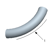
This example shows how to create a curve-driven solid tangent draft on one side of the sketched reference curve (1). In this example, the feature is added in Part mode.
1. Create a flat surface that passes through the part, as shown in the following illustration.
2. Click Model > Surfaces > Blend Tangent to Surfaces. The Tangent Surface dialog box opens.
3. Select One Sided under Direction.
4. To specify the pull direction, select the surface created in Step 1 and click Okay.
5. Click the
References tab, click

under
Draft Line Selection, and select the reference curve.
6. Select the Tangent To reference curve (the default is automatic) and click Done.
7. Click

under
Parting Surface and select the surface created in Step 1.
8. Click

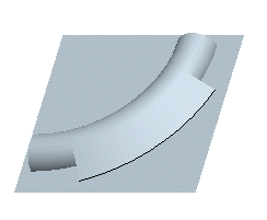
. The tangent draft is created on one side of the reference curve, according to the pull direction, as shown in the following illustration.
9. Click the Options tab, type 30 in the Cap Angle Value box, and press ENTER.
10. Click

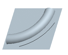
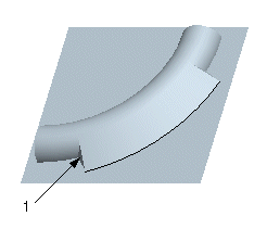
. The angle of the planar surfaces (1) changes on both sides of the tangent draft feature, as shown in the next illustration.
11. Depending on your design intention, you may want the tangent draft to extend the complete length of the part. Therefore, instead of specifying the
Cap Angle, click

under
Select Surfaces on the
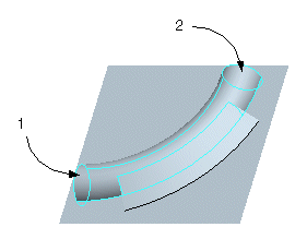
Options tab and select the two closing surfaces of the part (1 and 2).
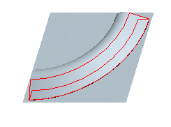
The resulting tangent draft geometry is shown in the following illustration.
|  Depending on the draft line geometry, the system may or may not be able to extend the draft surface up to the closing surfaces. It is recommended that you use appropriate tools to create and modify curves to ensure that the draft line extends up to or past the intended closing surfaces, and then create a tangent draft. |

 under Draft Line Selection, and select the reference curve.
 under Parting Surface and select the surface created in Step 1.
 . The tangent draft is created on one side of the reference curve, according to the pull direction, as shown in the following illustration.
 . The angle of the planar surfaces (1) changes on both sides of the tangent draft feature, as shown in the next illustration.
 under Select Surfaces on the Options tab and select the two closing surfaces of the part (1 and 2).