Example 7: Topology Design of a Compliant Mechanism
Use the model compliant.prt for this example.
Description
This example demonstrates how to use topology optimization to design a compliant mechanism.
Highlighted features
Compliant mechanism, Maximize Reaction Force, Mass Fraction constraint, Symmetry fabrication constraints
Optimization problem statement
For the design of compliant mechanisms, the objective is to find the structural configuration that deforms to a prescribed direction instead of making it as stiff as possible.
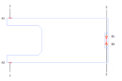
1. Input points
2. Output points
The upper and lower corners on the left side show input points A1 and A2. As these two points are squeezed together, the final design will squeeze output points B1 and B2 together. The ratio of the output reaction forces and the input forces is called the mechanical advantage of the compliant mechanism.
The optimization formulation for this problem will include enforcing a given displacement at points A1 and A2 as the input. At points B1 and B2, we constrain all the motions, and maximize the reaction forces in the vertical direction.
The following optimization problem will be created and solved:
• Objective:
◦ Maximize reaction force at output point B2
• Subject to:
◦ Mass fraction <= 0.3
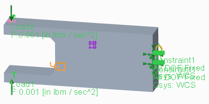
Analysis
The example contains one analysis. The loads/constraints are shown in the image below:
Mesh control
Maximum element size: 0.2 inch
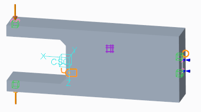
Topology region
• References:
The component, excluding volume region 1, 2, and 3, as shown in the image below.
• Init. mass fraction: 0.3
When mass fraction is used as a constraint, it is recommended to use the same constraint bound value as the initial mass fraction value.
• Fabrication constraints:
◦ Mirror symmetry about the XY plane with respect to coordinate system CS0
◦ Mirror symmetry about the XZ plane with respect to coordinate system CS0
◦ Minimum member size: 0.4 inch
It is recommended to set the Minimum member size to at least twice that of the mesh element size.
◦ Spread fraction: 0.5
Design objective
Maximize reaction force at point B2, component translation 3 (along positive Z direction)
Design constraints
Mass fraction <= 0.3
Optimization study
The study refers to the defined topology region, design objectives, and constraints
Advanced settings:
• Max. Design Cycles = 30
• For analysis output files, only the first and last cycle are requested.
• Use default settings for all other analysis and design parameters.
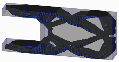
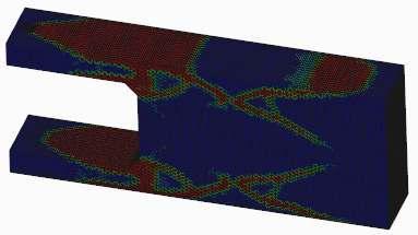
Topology Result
• Topology density isosurface
• Topology element density
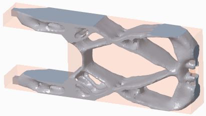
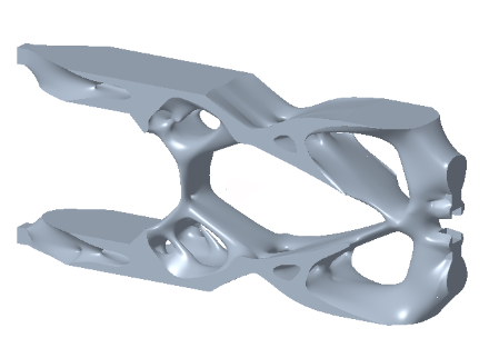
Geometry Reconstruction
• Tessellated model
• Solid model