Gaps in Parts
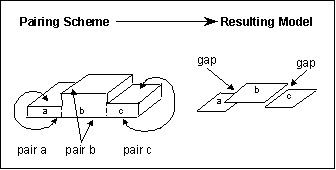
Depending on how you pair your single-part model, Creo Simulate can encounter gaps in the midsurface. A gap is a section of the model where the midsurfaces do not meet.
Gaps often occur in portions of a solid model that are not symmetric. In asymmetric models, various sections of the model have different thicknesses and the midsurfaces of the sections do not coincide. Thus, if you define individual shell pairs for each thickness, the midsurfaces do not meet.
In addition, gaps can occur in Sheetmetal models, depending on how you create your features. This situation results from the fact that Sheetmetal does not typically merge common feature faces, or wall junctions.
In the following solid model, there are two gaps:
Be aware that no modeling information passes between gaps. For example, if you create a constraint set that fixes the far end of section a for the model shown above, sections b and c would not see this constraint.
Gaps can cause problems during analysis. If Creo Simulate analyzed the example model using the constraint set just described, the software would interpret the model as three independent bodies, only one of which is constrained. Because the model contains unconstrained bodies, Creo Simulate would display an error message and halt the analysis.
You can correct this problem by inspecting the model closely for gaps. When you locate a gap, you can do one of the following:
When you define variable thickness pairs for asymmetric models, minor shape differences can occur between the Creo Parametric part and the analyzed model. Before using variable thicknesses, determine whether this type of shape change is acceptable in terms of the results you want Creo Simulate to provide.
• Rework the part geometry in Creo Parametric to improve midsurface coincidence.
• Treat the model as a solid instead of a shell.
• For Sheetmetal, rework the features using the Merge Wall command. For information on merged walls and how to create them, search the Sheetmetal functional area in the Creo Parametric Help Center.

