Beam Shape Coordinate System
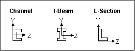
Creo Simulate defines the beam cross-section shape relative to the beam shape coordinate system (BSCS). The X axis for beams is along the length of the beam, with the positive X direction determined when you select the
beam references. For standard beam section types, the software determines the Y and Z axes for the BSCS. Here are a few examples of BSCS for standard beam sections:
If you create a sketched beam section, the orientation of the Y and Z axes for the BSCS is the same as the orientation of the Y and X axes in the sketcher. For a general cross section, the software determines the BCPCS based on your specifications, and the BSCS is essentially the same as the BCPCS for this cross-section type.
When Creo Simulate draws the beam section outline as part of the beam icon in the model window, it also draws the BSCS, with a Y-shape at the tip of the Y axis and an arrow at the tip of the Z axis.
You can position the origin of the BSCS relative to the BACS by entering values for DY and DZ on the Beam Orientation Definition dialog box. You can also rotate the BSCS around the beam X axis by entering a value for Orientation Angle on the same dialog box. As an alternative adjustment, you can click the Shear Center radio button to position the shear center of the beam section relative to the BACS. When you assign a beam orientation to your beam, Creo Simulate adjusts the beam icon in the model window to reflect the rotational and linear offsets.

