Components for Bearing Connection Reaction Measures
A bearing connection allows translation and rotation along and around an axis, and rotation around two axes perpendicular to the first axis.
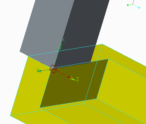
As shown in the illustration below, the Z axis of a bearing connection is fixed to the LCS of the first (green) body and can be positioned anywhere along the bearing translation axis. You can only define meaningful Radial Force X and Radial Force Y measures in relation to the first (green) body LCS. In other words, you cannot define Radial Force X in relation to the bearing translation axis because it is fixed to the first (green) LCS.
You can define the following measures for a bearing connection:
• Axial force—the force component as it moves along a translation axis (Force X, Force Y, and Force Z).
• Radial force X and Radial force Y—the force component on the plane perpendicular to the Z axis of the connection.
• Total Force
Depending on the type of component you are defining in the Definition dialog box, you can expect the following results:
• If you select Radial force X or Radial force Y, the axis line of the first (green) body is displayed at the connection icon and the X and Y directions are clearly visible.
• If you select Total force, Axial force, or Radial force, the values are scalar and a LCS reference is not necessary.
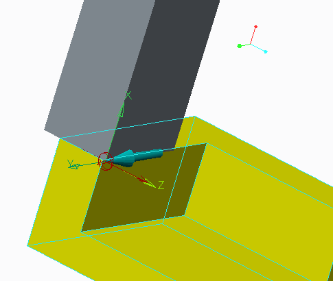
When Force X, Force Y, or Force Z is selected, the connection icon, the X, Y, and Z directions, and the direction of the force are clearly visible (see below).
• When you select the bearing connection and Axial force, a colored arrow appears on the connection indicating the positive direction. Consider carefully whether this direction correctly indicates the force or moment you want to display.
• If your model is shaded, the shading may hide the arrow. Select the Wireframe, Hidden Line, or No Hidden display to make the arrow visible.
• These forces are displayed in the bearing point when you run the playback file.


