About Surfaces for Cam-Follower Connections
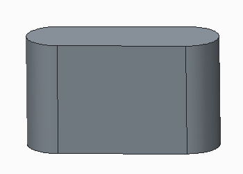
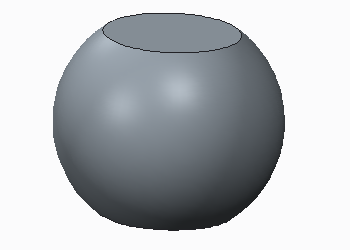
You can select any set of contiguous, extruded surfaces belonging to a single body. Extruded surfaces must be perpendicular to the plane on which the curve lies. The surfaces can curve in only one direction (they cannot bow).
For example:
|
Acceptable Surface
|
Unacceptable Surface
|
Surface curves in one direction |
Surface is bowed |
When selecting surfaces, be aware of the following information:
• You can select a surface that has arbitrary trimming, including, for example, interior holes and extrusion depth variations.
• You can select surfaces with different extrusion depths.
• If you select the Autoselect check box before you select a curved surface, any surfaces adjacent to the selected surface will be included. The surfaces may not be continuous, so be sure to examine them to determine whether you need to smooth the geometry. You cannot use the Autoselect option with curves or flat surfaces.
• If your cam bodies have sharp or discontinuous surface transitions, modify the geometry before creating the cam-follower connection to avoid poor performance. For example, you can create a small round feature on the sharp corner.
• The side of the cam that interacts with a second cam is indicated by the direction of the cam normal. If you select an open curve or surface, a magenta arrow appears indicating the cam normal, which extends from the interacting side. If you want to change the cam interaction to the back of the cam, click Flip on the Cam-Follower Connection Definition dialog box. Keep in mind that changes to the cam interaction must satisfy the geometry and assembly constraints of the model.
• You can select planar surfaces, but for flat surfaces you must also specify additional references for the cam extrusion direction. To explicitly specify the cam direction, click Front reference and Back reference on the Cam-Follower Connection Definition dialog box.
• To change the cam surface definition on an existing cam, select it from the Mechanism Tree, then right-click and choose Edit Definition from the shortcut menu. The Cam-Follower Connection Definition dialog box opens. You can select a surface or curve to remove from either cam by holding down the CTRL key as you select, or you can Flip the surface normal.


