About Using Flexible Modeling Tools on Sheet Metal Parts
When you use the Flexible Modeling tools that are not sheet metal specific to edit sheet metal parts, design objects are treated as intent surfaces.
You can use the base Flexible Modeling tools on sheet metal parts as follows:
• Modify group:
◦ Edit Round—Recreates round geometry.
◦ Edit Chamfer—Recreates chamfer geometry.
• Transform group:
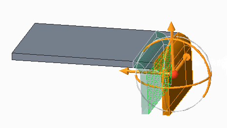
◦ Move—Use the
Move tool to move geometry. When you select geometry to move, all surfaces needed to recreate the geometry correctly are selected. In the figure below a surface was selected to move, the bend is also selected and moved with the surface. When you move a sheet metal surface, you cannot use the keep existing tangency

option. After moving sheet metal geometry, you can unbend the part or create a flat pattern to check for overlapping geometry.
◦ Offset—Use the Offset tool to offset sheet metal side surfaces.
◦ Substitute—Use the Substitute tool to replace sheet metal side surfaces.
◦ Modify Analytic—You cannot use the Modify Analytic tool to modify sheet metal surfaces. You can use this tool to modify simple surfaces such as those of cuts and holes.
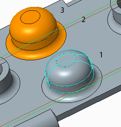
◦ Mirror—Use the Mirror Geometry tool to mirror selected geometry about a plane. When you select geometry to mirror, all surfaces needed to recreate the geometry correctly are selected.
1. Original selected geometry
2. Mirror plane
3. Mirrored geometry including adjacent rounds
◦ Flexible Pattern—Use the Pattern tool to create multiple instances of a feature according to the type of pattern selected. When you select sheet metal geometry to pattern, all surfaces needed to recreate the geometry correctly are selected.
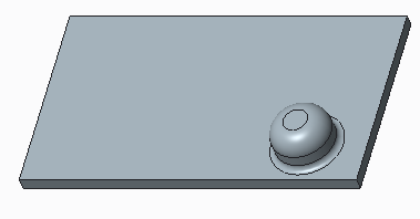
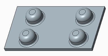
The figure below shows a simple form.
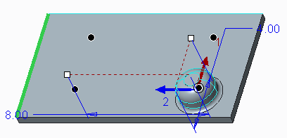
The figure below shows the selected form being patterned using a direction pattern.
The figure below shows the resulting pattern of forms including round geometry.
• Recognition group:
◦ Pattern—Use the Pattern Recognition tool to identify geometry that is identical or similar to selected geometry. You can manipulate the recognized pattern as a single feature.
◦ Symmetry—Use the Symmetry Recognition tool to identify geometry that is symmetrically identical to geometry selected. You can select a datum plane as the plane of symmetry.
◦ Click Recognition to display the following commands:
▪ Chamfers—Use the Recognize Chamfers and Not Chamfers commands to recognize geometry as Chamfers or Not Chamfers.
▪ Rounds—Use the Recognize Rounds and Not Rounds commands to recognize geometry as Rounds or Not Rounds. Geometry recognized as Not Bends can be recognized as Rounds.
• Edit Features group
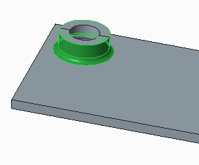
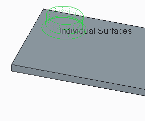
◦ Remove—Use this tool to remove geometry. It is enough to select surfaces to remove a sheet metal object.
The figure below shows the outside surfaces of a form selected.
The figure below shows the preview in the Remove tool for the selection above. The entire form is removed when the surfaces are selected.
For more information on the Flexible Modeling tools, search for Flexible Modeling in the Help Center.