Example: Block Boundary Based Pipe Piece Cutting
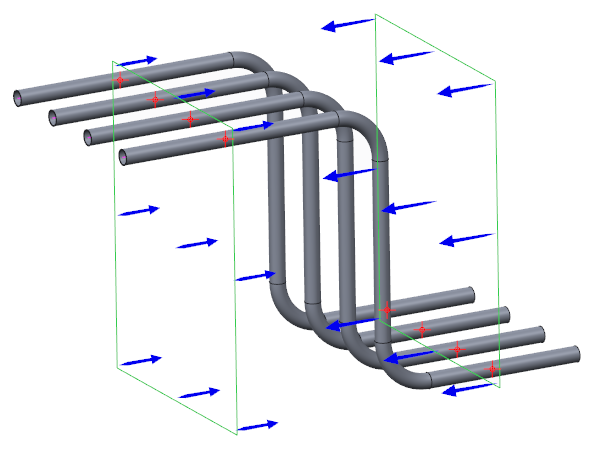
The following figure shows a set of pipelines (magenta) within the block BLOCK1002A. The boundaries of the block are highlighted.
Use the following procedure to create pipe piece cuttings based on the block boundary:
• Click
 Cut
Cut.
• Click

to cut pipe pieces based on the block boundary.
• Select BlOCK1002A from the Select Block selection list.
Spec-Driven Piping selects all pipelines in the specified block for creation of the pipe piece cuts. The labels of all the pipelines that intersect with the selected block are displayed under Pipelines To Be Cut.
All locations where the pipelines intersect with the block boundary are highlighted as shown in the figure above.
Information such as the total number of intersections and details of the intersections is displayed in the message window as shown:
◦ 2 intersections found for the pipeline 100A-MS-STEAM-0001.
◦ 2 intersections found for the pipeline 80A-MS-STEAM-0002.
◦ 2 intersections found for the pipeline 10A-MS-STEAM-0003.
◦ 2 intersections found for the pipeline 80A-MS-STEAM-2004.
◦ Total intersections found : 8
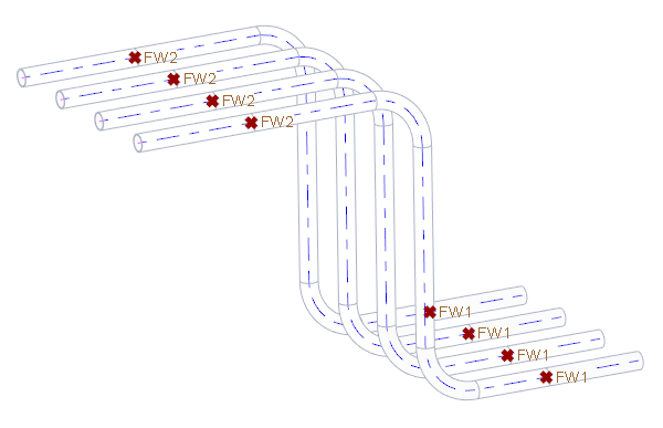
• Click OK to create a pipe piece cuttings as shown in the following figure. The pipe pieces are created at locations where pipeline intersect block boundary.
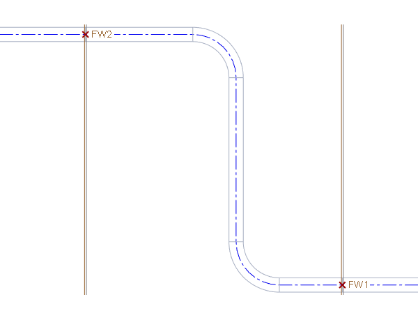
These cut point locations depend on the block boundaries. The dimension for the cut points is not displayed in the figure because the driving dimensions of the block boundary geometry control the locations of these cut points.
For example, the preceding figure shows the dimension of the block boundaries ADTM1 and ADTM2, The dimension of both the boundaries is 75.00.
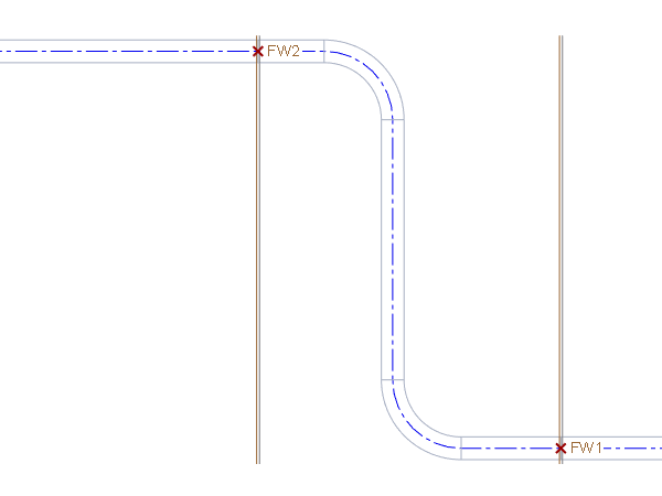
If you modify the dimension of ADTM1 and ADTM2 to 40.00, the cut points on those boundaries also move along with the bounding geometry as shown in the following figure.