Assembling Free Port Fittings
Use the sample files provided at
<Creo load point>\Common Files\help\sample_models\piping when working in this exercise. It is recommended that you create a copy of the
piping folder on your computer and
set up piping data before you start working with the tutorial.
Create Pipe Segments
1. On the
Home tab, click
 New
New. The
New dialog box opens.
2. Under
Type, select
 Assembly
.
3. Click OK to create a new assembly.
4. Click
Applications >
 Piping
. The
Piping tab opens.
5. On the Piping tab, select the Spec Driven check box.
6. Click
 Create Pipe
. The
Create Pipeline dialog box opens.
7. In the Size box, select 100A.
8. In the Number box, type 1.
9. Click OK. The Create Pipeline dialog box closes.
10. Click

and select the
Pipeline View check box. The Piping System Tree appears.
|  The newly created pipe 100A-MS-STEAM-1 appears on the expanded Piping System Tree. |
11. Click
 Insert Fitting
. The
Insert Fitting dialog box opens.
12. Select ASM_DEF_CSYS in the graphics window as the reference.
13. Under
Fitting, click

. The
Insert Fitting dialog box updates.
14. In the Selection name box, select ELBOW90LR.
15. Click the Placement / orientation tab. The first fitting appears in the graphics window.
16. Click Apply. Another fitting is added.
17. Click Apply again. One more fitting is added.
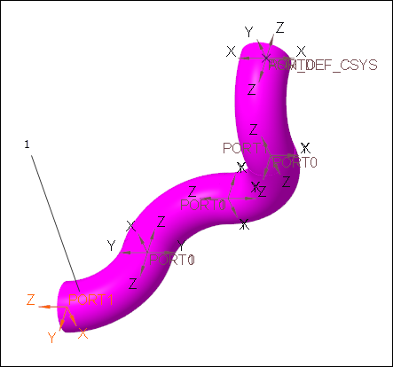
18. Under Rotation angle, select 90. The last fitting is rotated by 90 degrees.
19. Click Apply again. One more fitting is added.
20. Under Rotation angle, select 270. The last fitting is rotated by 270 degrees.
21. Click OK. The Insert Fitting dialog box closes.
22. Expand the 100A-MS-STEAM-1 node on the Piping System Tree. The newly added elbows appear.
23. Click
 Route Pipe
.
24. Click
 Set Start
. The
Define Start dialog box opens.
25. Select PORT1 related to the last elbow fitting as the reference.
1. Port1
26. Click OK. The Define Start dialog box closes.
27. Click
 Extend
. The
Extend dialog box opens.
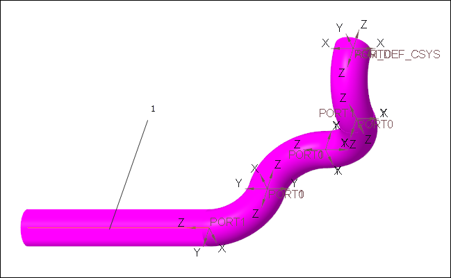
28. In the z box, type 600 and press ENTER.
29. Click OK. A pipe segment is created.
Insert a Fitting
1. Click
Insert Fitting. The
Insert Fitting dialog box opens.
2. Select the last pipe segment in the graphics window.
1. Pipe segment
3. In the
Insert Fitting dialog box, click

to select the reducer fitting.
4. Click the Placement / orientation tab. A preview of the fitting appears.
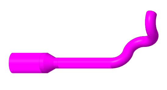
5. Click
 Flip
Flip. The inserted fitting flips.
6. Click OK. The Insert Fitting dialog box closes.