|
Fitting Parameter
|
Description
|
||
|
Fitting Branch Size Parameter
|
The branch size parameter must be inserted on the branch port of a fitting. It is a string type feature parameter denoted as BRANCH_SIZE. This parameter accepts any valid pipe nominal diameter value. Insert this parameter only if the branch port size of a fitting is different from its inlet port size.
You can define a single reducing tee fitting by inserting the SIZE parameter on the inlet port and the BRANCH_SIZE parameter on the branch port.
|
||
|
Flow Constrained Fitting Parameter
|
The FLOW_CONSTRAINED parameter is an integer type Part parameter. Insert FLOW_CONSTRAINED on the library part for flow direction specific fittings such as a Check Valve and unidirectional angle valves.
The FLOW_CONSTRAINED parameter is used as a status flag by the flow direction reversal functionality for flipping the fitting during flow reversal. Because this integer parameter is used as a status flag, its value is ignored by the software.
The assignment of a value for an integer parameter is mandatory. You must assign an integer value (such as 1) consistently, but it is not used by the software.
|
||
|
Fitting Inlet Size Parameter
|
The Fitting Inlet Size parameter is inserted only on one of the ports of a fitting. It is a string type feature parameter denoted as SIZE. A fitting port that has the SIZE parameter is designated as the inlet port of the fitting. This parameter accepts any valid pipe nominal diameter value. The size values assigned to this parameter must match the size values that you have specified in various master catalog files.
|
||
|
Fitting Outlet Size Parameter
|
The fitting outlet size parameter is inserted on the outlet port of a fitting. It is a string type feature parameter denoted as NEW_SIZE. This parameter accepts any valid pipe nominal diameter value. Insert this parameter only if the outlet port size of a fitting is different from its inlet port size. The nominal value of the NEW_SIZE should be less than nominal value of the SIZE.
|
||
|
Fitting Eccentricity Parameter
|
The fitting eccentricity parameter must be inserted on a library part of an eccentric fitting and is applicable only for a fitting that has either the inlet or the outlet port eccentricity along the local y-axis of the fitting. It is an integer type part parameter denoted as Y_ECCENTRICITY. This parameter generally behaves like a status flag and its value is not relevant.
The Y_ECCENTRICITY parameter behaves like a status flag while inserting eccentric fittings, for enabling the centerline offset.
|
||
|
Surface Area Parameter
|
The surface area is assigned directly to a fitting library part using the real value parameter PRO_MP_ALT_AREA. Specify a value for the PRO_MP_ALT_AREA parameter in the same system of unit for area, as specified for the fitting library part.
The surface area of a fitting library part is calculated when you perform the model analysis of a pipeline assembly using the Model Analysis dialog box. If you have specified the value PARAMETERS for the PRO_MP_SOURCE parameter, Creo Parametric uses the value that you have specified for PRO_MP_ALT_AREA for the fitting, and relates it to the analysis parameter PRO_MP_AREA, to calculate the surface area. If you do not specify any value for PRO_MP_ALT_AREA, or if you specify the value GEOMETRY for the PRO_MP_SOURCE parameter, the geometry of the fitting library part is used for surface area calculations.
|
||
|
Center of Gravity Parameters
|
You can directly assign the center of gravity for a fitting library part using the real parameters, PRO_MP_ALT_COGX, PRO_MP_ALT_COGY, and PRO_MP_ALT_COGZ. The values that you assign for PRO_MP_ALT_COGX, PRO_MP_ALT_COGY, and PRO_MP_ALT_COGZ are used for center of gravity calculations if you specify the value PARAMETERS for the PRO_MP_SOURCE parameter. If you do not specify any values for the center of gravity parameters, or if you specify the value GEOMETRY for the PRO_MP_SOURCE parameter, the geometry of the fitting library part is used for center of gravity calculations.
Spec-Driven Piping automatically updates the center of gravity information when you modify or replace a fitting.
The Report Pipeline dialog box reports the center of gravity information if you select COG_X, COG_Y, or COG_Z as the columns in the Report Format dialog box. In case of fittings, if you assign PRO_MP_ALT_COGX, PRO_MP_ALT_COGY, and PRO_MP_ALT_COGZ parameters to a fitting, Spec-Driven Piping transforms these parameters with respect to the start location of the pipeline and reports the center of gravity information. The x-, y-, and z- coordinates of the center of gravity of pipe segments and fittings are reported in the linear units of the piping assembly.
|
||
|
Weight Parameter
|
You can assign the PRO_MP_ALT_MASS parameter to library parts for weight calculation. The Model Analysis feature uses this parameter along with other user-defined parameters for the appropriate model analysis calculations.
If you have set the value of the PRO_MP_SOURCE parameter to PARAMETERS, Model Analysis uses the associated value for mass property calculations. If the value for the PRO_MP_SOURCE parameter is set to GEOMETRY, or if you have not assigned values for other parameters, Model Analysis uses the geometry of the part for model analysis calculations.
|
||
|
Valve Number Fitting Parameter
|
The valve number parameter is assigned to a fitting component feature. It is a string type parameter denoted as VALVENUMBER.
|
||
|
Fitting Alignment Offset Parameter
|
The fitting alignment offset parameter is an optional parameter and can be inserted on any selected port of a fitting with an appropriate offset value. It is a real type feature parameter denoted as OFFSET. The value of the OFFSET parameter must be the distance between a port and its corresponding face. It is mainly used for socket-welded and screwed fittings. The following figure shows a screwed valve: 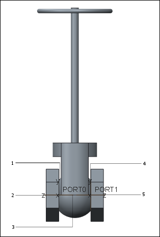 1. Upstream Port OFFSET = 20.0 2. Near Point (20 mm from Port Origin 3. Automatic Center Point 4. Downstream Port OFFSET = 20.0 5. Far Point (20 mm from Port Origin) The fitting insertion functionality provides an additional option to enable alignment based on the OFFSET parameter. If you enable this option during fitting insertion, the NEAR/FAR alignment locations are determined using the respective port and the OFFSET parameter on it. The OFFSET parameter is also used for interference checking between two adjacent fittings. The following points must be noted while assigning offset parameter values to a fitting: • Assign only positive values. The system ignores negative values, and in this case an absolute value is used as the offset. • When you use the offset value that is associated with a given port, the optional alignment location for the port is offset along its positive z-axis. • If a port has the same end type and offset value as the inlet port, specify the OFFSET parameter only for the inlet port. • If a port has a different end type as the inlet port, you must specify an OFFSET parameter for that port and assign appropriate values depending on the end type of that port. When the end types are different, the offset value specified for the inlet port will not be applicable to the other port. |
||
|
Fitting End Type Code Parameter
|
The end type parameter must be inserted on the inlet port of a fitting with appropriate end type values. It is a string type feature parameter denoted as END_TYPE. It is mandatory to insert this parameter on the inlet ports of all the fittings.
If all the ports of a fitting are of the same end types, you need not assign this parameter to all the ports. It is sufficient if you assign the END_TYPE parameter to the inlet port. If a fitting does not have an END_TYPE parameter in its outlet or the branch ports, the system automatically assigns the END_TYPE parameter specified for the inlet port to all the other unspecified ports. However, if a fitting has different end types for its inlet, outlet and branch ports, an END_TYPE parameter needs to be inserted with appropriate values at the inlet, outlet or the branch ports. The system uses these specified end types for the respective ports.
The end type values that are used for fitting end types in the supplied library and the fitting MCAT files are as listed:
• BW—Butt Welded
• SW—Socket Welded
• SC—Screwed
• SO—Slip On
• FLFF—Flanged Flat Face
• FLRF—Flanged Raised Face
• FLRJ—Flanged Ring Joint
• FLTG—Flanged Tongue end of Tongue and the Groove mating
• FLGR—Flanged Groove end of Tongue and Groove mating
The END_TYPE parameter is used while inserting fittings for performing automatic end type checking between the adjoining fittings. It is also used for automatically inserting mating flanges and gaskets when you insert flanged fittings.
|