Example: Prevent Shell from Penetrating at Convex Corners
This example shows you how to create a Shell feature by excluding surfaces and preventing the shell from penetrating at convex corners.
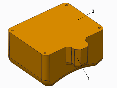
Create a shell feature as described in another example. Follow the steps below to exclude surfaces from being shelled and prevent the shell from penetrating at convex corners. The original model is shown in the following illustration.
1. Convex corner
2. Surface to remove
1. Open the References tab and click the Removed surfaces.
2. Select the side surface (2) as the surface to remove.
3. To exclude surfaces from the shell process, open the Options tab and click the Excluded surfaces collector.
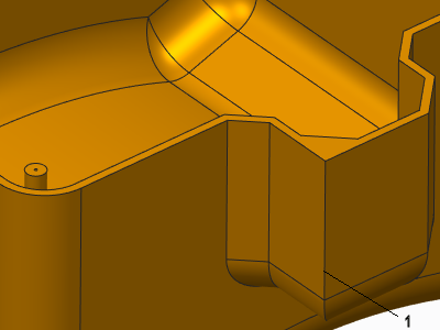
4. Select the surface to exclude in the graphics window as shown in the following illustration.
1. Surface to exclude
5. Click the Options tab and select Convex corners under Prevent shell from penetrating solid at.
6. Click

. The model, after shelling, is shown in the following illustration.
1. Shelling prevented at convex corner