1. Click Model >  Draft. The Draft tab opens.
Draft. The Draft tab opens. Draft. The Draft tab opens.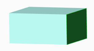
• You can also select one or more draft surfaces before entering the Draft tool. • You can also click Details to open the Surface Sets dialog box to collect surfaces. • You can select open surfaces as draft surfaces. An open surface is a surface that has at least one one-sided edge. |
 collector on the Draft tab and select a plane, a quilt, or a curve chain located on the draft surfaces.
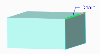
 collector on the Draft tab and select a plane (in which case the pull direction is normal to this plane), a straight edge, a datum axis, or an axis of a coordinate system. The pull direction is the direction you would pull the part out of a mold.
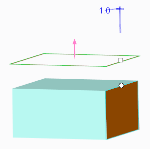
 box. Two drag handles are also shown, a round one, located on the draft hinge or on the draft surface contour, and a square one, connected to the draft angle. box on the Draft tab. You can also drag the square handle connected to the draft angle, or double-click the draft angle value in the graphics window and type or select a value.
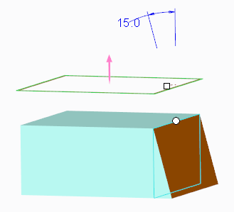
 to the right of the box to add or remove material. You can also drag the square handle connected to the draft angle to the other side of the part surface to which it is attached, or type a negative draft angle value.
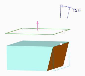 to the right of the collector on the Draft tab, or click Flip on the References tab.
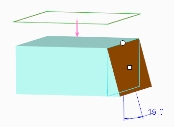
 .
.