About Point Patterns
You can create a pattern by placing pattern members at points or coordinate systems. Create or select any of the following references when you use a Point pattern:
• A sketch feature that contains one or more geometry sketch points or geometry sketch coordinate systems.
• An internal sketch that contains one or more geometry sketch points or geometry sketch coordinate systems.
• A datum point feature
• An import feature that includes one or more datum points
• An analysis feature that includes one or more datum points
When you create a point pattern, the system creates pattern members by placing the origin of the lead feature or geometry at each of the points or coordinate systems. This can be seen in the pattern preview where the origin of the lead member is shown as

, and the locations where that origin will be placed for each additional pattern member are shown as

.
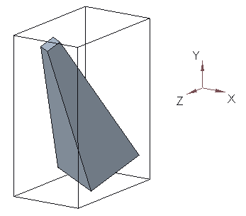
By default, the origin of the lead feature or geometry is at the center of an imaginary bounding box around the feature or geometry. The bounding box is the smallest possible rectangular box that includes all of the feature or geometry. The sides of the bounding box are parallel to the x-, y-, and z- axes of the default coordinate system of the model. The box is not visible, it is shown here for purposes of explanation.
So, by default, the system places the center of the lead pattern member at each of the point pattern locations. However, if the lead member of the pattern uses a point as a reference, then the system automatically uses this point as an alternate origin. The same applies if the lead member of the pattern uses a coordinate system as a reference.
You can tell the system to use an alternate origin when placing the pattern members by selecting the Use alternate origin collector, and selecting a different entity to use as the origin. This gives you greater control over how the pattern members are created, and can be used if you are not satisfied with the default. You can also remove the default origin that appears in the Use alternate origin collector.
If you use sketched entities, make sure they are geometry entities. Construction entities are sketching aids only, and they do not convey feature-level information outside Sketcher.
The sketch you reference may also include curves. When you select the Follow curve direction option on the Options tab, each pattern members is oriented to reflect the curve tangent direction, where its point coincides with the curve. If you clear the Follow curve direction check box, any curves present in the sketch are ignored.