About the Lattice Feature User Interface
The
Lattice tab consists of commands, tabs, and shortcut menus. Click
Model >
Engineering >
 Lattice
 to open the
Lattice tab.
Commands
• Lattice Type—Sets the type of the lattice. You can select 3D or 2.5D.
• 
—Defines which direction the Z axis of the cell is aligned with. You can select
Z Direction,
X Direction, or
Y Direction.
• 
—Defines how the cells are positioned in the internal volume. You can select one of the following:
◦ Regular—Fills the volume layer by layer.
◦ Quasi-radial—Fills the volume in a circular pattern.
▪ Base Cell Number—Sets the number of cells in a single circle.
◦ Herringbone—Fills the volume in zigzag pattern.
• 
—Toggles the lattice representation.
◦ Simplified—Creates a light-weight approximation of the lattice. The mass properties are also approximated. Using a simplified representation enhances performance. Simplified representations can’t be exported to 3D printers.
Starting in Creo 5, simplified lattices are included in the calculation of mass properties. For lattices saved before Creo 5, you must regenerate the model before simplified lattices are included.
◦ Full Geometry—Creates full lattice geometry that includes all properties and an accurate appearance. Full geometry representation requires more resources and might cause the system to be slow, particularly when the lattice contains a large number of lattice cells. Full geometry representations can be exported to 3D printers.
◦ Homogenized—Creates a special quilt with semi-transparent surfaces to represent the lattice volume.
• 
—Sets the size of the cell relative to its current cell size, keeping its current proportions.
Tabs
• References
Use this tab to enable, define, and display the lattice boundaries.
◦ Convert Solid check box—Converts solid parts to lattice. When Convert Solid is selected, the following options are also available:
▪ Keep Shell check box—Includes the shell of the solid as a part of the lattice. When this option is selected, the following options become available:
▪ Thickness—Controls the thickness of the shell.
▪ Shell Side—Controls the direction in which the shell is created. You can choose Inside or Outside.
▪ Excluded Shell Surfaces collector—Displays the surfaces that are excluded from the shell.
▪ Details—Displays the relevant surface sets.
◦ When Convert Solid is cleared, the following options are available:
▪ Bounding Surfaces collector—Displays the surfaces that define the internal volume of the lattice.
▪ Details—Lists the bounding surfaces sets.
◦ First Cell Location collector—Selects a coordinate system as the location for the first lattice cell. The automatically selected location is the origin of the default coordinate system.
◦ Patch Open Areas check box—Creates bounding surfaces in open areas, such as holes.
◦ Skip Failed Geometry check box—Does not add lattice elements in places where geometry fails.
• Cell
Use this tab to define the cell parameters.
◦ Cell Shape—Defines the shape of the lattice cell.
◦ Cell Size—Defines the X, Y, and Z dimensions of the cell. These are the absolute cell dimensions, using the model units.
◦ Skewing Angle—Defines the angle of cell slanting.
◦ Round Radius check box—Defines the radius of the rounded edges. The round radius is ignored when you create lattice with varied density.
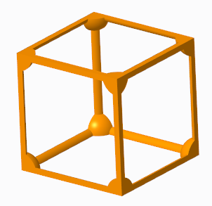
◦ Cell Configuration—Sets which types of beams are a part of the cell in 3D lattice.
▪ Clear all—Clears all beam types.
▪ Custom—Enables user-defined selection combinations. For triangular-, square-, or hexagonal-type lattice, controls the internal structure of the cell by defining which types of beams are included in or excluded from the structure.
▪ Inner Horizontal Beams and Inner Vertical Beams used together
▪ Outer Horizontal Beams and Outer Vertical Beams used together
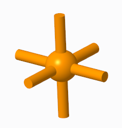
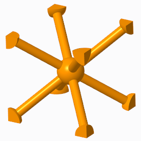
▪ Star—Selects only Angular Beams.
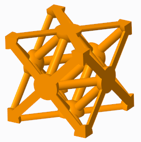
▪ Truss—Selects only Outer Truss Beams and Inner Truss Beams. Available for Square and Triangular cell shapes.
◦ Remove Dangling Beams—Removes beams that are not attached to a solid or another beam on both ends in 3D lattice.
◦ Wall Thickness—Sets the thickness of the cell walls in 2.5D lattice.
◦ Add Drain Holes—Adds slot-shaped holes to the cells in 2.5D lattice. The following options are available:
▪ Width—Defines the width of the drain hole.
▪ Length—Defines the length of the drain hole.
▪ Spacing—Defines the distance between two drain holes.
• Beam
Use this tab to define and display the beams of the 3D lattice. It contains the following options:
◦ Cross Section Type—Defines the shape of the cross section of the beam.
◦ Cross Section Size—Defines the size of the cross section of the beam.
◦ Profile Type—Defines the shape of the beam. You can select Straight or Parabolic.
◦ Parabolic Radius—Sets the parabolic radius, when beams are set to have a parabolic profile.
◦ Profile Coefficient—Sets the coefficient of the profile, when beams are set to have parabolic profile.
◦ Ball Diameter—When Straight profile is selected, you can add balls at the corners where the beams intersect, and in the center of the cell, and set their sizes.
• Density
Use this tab to define lattice with varied density. The density is determined by the size of the cross section of the beam. It contains the following options:
◦ Variable Beams—Manages the sets. Each set defines a volume region.
◦ Distance—Defines the size of the area with regards to the reference where the varied lattice is created.
◦ Ref Cross Section Size—Sets the cross section of the beam, at the reference you specified.
◦ Rate of Size Change—Sets how quickly the beam size changes. When this option is set to 1, the rate of change is linear. When the value is smaller than 1, the rate is lower than linear. When the value is greater than 1, the rate is higher than linear.
◦ References—Defines the references that are used to create the varied density of a volume region. This reference can be a point, a curve, a coordinate system origin, or a surface.
◦ Minimal Beam Size—Defines when to stop creating the lattice.
◦ Tapered Beam check box—Sets whether beams can be tapered.
• Properties
Name—Defines the name of the lattice feature.