Object Properties
A tolerance analysis measurement contains the following object properties.
• Name—The name for parts and dimensions are initialized to the name of the related part or dimension in Creo Parametric. However, you can modify the names in the Measurement Table. Changing the name of a part or dimension within a tolerance analysis measurement will not affect the names of those objects in Creo Parametric
• Nominal—For dimensions, this value corresponds to the nominal value of the dimension inCreo Parametric. For measurements, this is the nominal value for the measurement based on the dimension loop. Note that this may differ from the value for a corresponding measurement in Creo Parametric depending on the attachment of any pin/hole interfaces in the measurement. You cannot modify any of the values in this column.
• Tolerance—This column shows the tolerance properties of the dimension based. The tolerance properties are initialized from the dimension properties in Creo Parametric. You can edit the tolerance properties of the measurement or a dimension by double-clicking the appropriate cell in the table.
|
|
 If the tolerance is from a part with the tolerance standard set to ISO and a tolerance table is driving the tolerance value, the tolerance limits cannot be modified from inside Creo Tolerance Analysis. The Precision setting can be changed. To modify those tolerance limits follow these steps: 1. Close Creo Tolerance Analysis.
2. Right-click the tolerance and click Properties. The Dimension Propertiesdialog box opens.
3. In the Tolerance Table box, select None.
4. Click Analysis > Tolerance. The dimension tolerance limits are now editable.
|
• Unit—For dimensions and measurements, this column shows the units of the CAD model that contains these objects.
• Cp—This value represents the capability index that is assumed for the dimension. The default value for Cp is defined in the application options, but you can modify the value for each dimension (0.5 >= Cp <= 3.0).
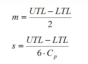
• Distribution—This column shows the statistical distribution parameters for the measurement and the dimensions. All dimensions are assumed to have a normal distribution. The mean (
m) and the standard deviation (
s) are calculated as follows:

Generally, the distribution for the measurement results will be normal. However, if you have included float for any pin/hole interfaces, the float variation introduces some non-normal effects that may result in a lambda distribution, which has four distribution moments. You cannot modify any of the values in this column.
• Sens—This column shows the sensitivity of the measurement to each dimension. For example, sensitivity value of -1.0 means that increasing a dimensional value by .1 would decrease measurement value by -0.1. The application automatically calculates the sensitivity for each dimension. You cannot modify any of the values in this column
• Attachment—An attachment is indicated for each dimension and each feature of size. Left or Right attachments are with respect to the orientation of the model as shown in the dimension loop diagram.
 Generally, the distribution for the measurement results will be normal. However, if you have included float for any pin/hole interfaces, the float variation introduces some non-normal effects that may result in a lambda distribution, which has four distribution moments. You cannot modify any of the values in this column.