PTC Creo ModelCheck Teacher: External References
An external reference is created when a feature of one component in an assembly references a feature in a different component. The references can take the form of dimensioning, aligning or sketching.
What causes external references?
They can be created for any of the following reasons:
• When working on a part in assembly mode.
• A part is created in assembly mode and sketcher or dimensioning references are made to features that belong to other parts.
• A feature of a part is redefined in assembly mode and sketcher or dimensioning references are made to features that belong to other parts or assembly features.
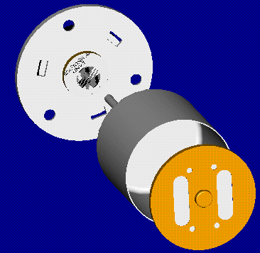
Example: In the assembly below, the orange disk was created in assembly mode using an offset edge reference from the outside surface of the gray cup. This gave the disk an external reference to the cup.
Why are external references dangerous?
If a model has an external reference, it becomes dependent on another model. This means that if you modify a dimension in a model to which another one is dependent, the next time you retrieve the dependent model, it may have changed unexpectedly.
In some cases you can use external references to your advantage, but do so carefully. An example of an effective use of external references is if you want to design a shaft that should always fit into a specific hole. Create the shaft in assembly mode with the part containing the hole already assembled. From SKETCHER, choose Use Edge and pick the edges of the hole as references. Now the diameter of the shaft will always be equal to the diameter of the hole. When doing this, make sure the part is not reused in another assembly, its dimensions will be driven from the original assembly, and unexpected things will happen.
If you want to create parts that have equal dimensions, such as in the above example, but do not want to create external references, follow this procedure:
1. Create the orange disk in assembly mode.
2. Set the diameter of the disk by using Use Edge on the surface of the cup.
3. Bring the disk up in part mode or by using Modify, Modify Part and redefine the protrusion that has the external reference.
4. Break the external references by unaligning, and dimension the diameter of the disk. Creo Parametric will not change the diameter of the disk, but will give it a value.
5. Now the disk has a diameter equal to the diameter of the cup, but does not reference it. The drawback of this is that if the diameter of the cup is changed, the diameter of the disk will not automatically update.
6. Add an assembly relation to set the diameter of the disk equal to that of the cup. The assembly relation will allow you to bring the disk into session in part mode and modify the diameter of the disk. The next time the disk is retrieved into the assembly, the relation will set its diameter to that of the cup.
How can external references be avoided?
• Always use default datum planes for all your parts and assemblies.
• When working on parts in assembly mode, be very careful how you dimension and reference your sketches. Always use Query Select to ensure you are dimensioning to entities on the same part.
• As of Revision 18.0, Creo Parametric has a Design Manager (Design Mgr) which is available within the ASSEMBLY menu. The Ref Control and Ref Viewer menu options allow you to investigate external references and to set the scope as to how components can be referenced.
• The use of assembly relations can be an effective way to drive dimensions in assemblies without creating external relations.

