All Geom Type Checks
When you click the All Geom Type tab in the Geometry CHECK (VDA standard) dialog box, a tabbed page appears. This page contains the following checks:
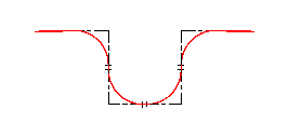
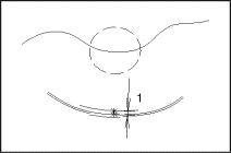
• Tiny Elements
◦ In wire geometry (default check setting: > 0.02 mm):
1. TOL
GeomIntegrityCHECK reports the elements in your model that are smaller than specified in your configuration files. It also suggests the changes that would make the model VDA-compliant. For example, you can delete a reported tiny element if it is not required for development of higher-ranking geometry.
Elements that fall short of a specific size in particular geometric operations (such as scaling and generation of offsets), in exchange of data (for example, with a system of lesser accuracy), or through further processing can lead to invalid elements and, consequently, to gaps. These elements usually occur through creating rounds and through closing mechanisms during bridging of small gaps or by overlapping.
Recommended solution:
Make the tiny elements superfluous by extending (extrapolating) the elements to be joined. Then delete the tiny elements. Alternatively, enlarge the tiny elements and correspondingly shorten the elements to be joined.
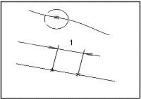
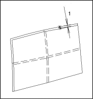
◦ In surfaces (default check setting: > 0.02 mm):
1. TOL
GeomIntegrityCHECK reports the faces and face patches whose length in at least two opposing directions is smaller than specified in your configuration file. This error can result in defective elements due to changes in the system or in the tolerance range. However, deletion of the faces or face patches can lead to gaps in the topology.
In addition, faulty tiny elements require larger storage space and increase the likelihood of continuity problems. These elements often occur as a result of system automation and the automatic closure of gaps in the when data is imported from other systems.
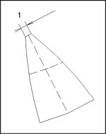
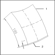
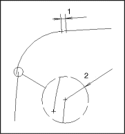
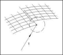
GeomIntegrityCHECK also reports the patch strips whose smaller extents have a less than 1:100 proportion in relation to a neighboring patch. Such size ratios are a sign of poor partitioning.
1. Patch 1
2. Patch 2
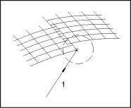
GeomIntegrityCHECK marks ten equidistant points on each of the four boundary or segment curves. Then it calculates the chord length from the resulting traverse paths. If all four chord lengths or two opposing chord lengths of an element are smaller than the 1% tolerance specified in your configuration file, in comparison to a neighboring segment, the element is reported.
Recommended solution:
Avoid tiny elements or make them superfluous by enlarging and subdividing the neighboring elements.
|  A surface is the base face of a part that can protrude beyond the contours of the part. Surfaces are generally bounded with simple mathematical boundary curves and usually serve as a surface for the bounded surfaces with complex edge curves. |
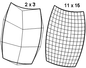
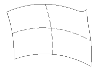
Surfaces can be composed of several segment faces called patches. These can be bound within the bounds of internal tolerances for position and gradients. Depending upon the number of segments (n, m) of the boundary curve, a surface is formed from a group of (n) times (m) patches.
◦ In bounded surfaces:
GeomIntegrityCHECK reports bounded surfaces that are smaller than specified in your configuration file. It calculates the face contents of a bounded surface and compares them with the VDA minimum value for that check.
Faces that fall short of the value in your configuration file can lead to invalid elements and thereby to gaps, especially with certain geometrical operations (for example, scaling formation of offsets), during the exchange of data (in a system with inferior exactness), or by subsequent processing (NC).
Recommended solution:
Delete the bounded surface. Enlarge and adapt the neighboring elements accordingly.
|  Clearly defined faces, also called bounded surfaces, or faces, describe the geometrical surface of an object, if applicable, inclusive of holes, indentations, recesses, and so on, on the surface that forms the basis with boundary curves that are projected upon it. The boundary curve is an endless continuous curve. |
◦ In solids:
1. &=TOL
GeomIntegrityCHECK reports the solids whose expansion in two spatial directions is smaller than specified in your configuration file.
The three main directions of expansion (for example, the main axis of inertia) in a rectangular solid are examined. If the extension of the solid is smaller in two coordinate directions than specified in your configuration file, the element is reported.
The volume of the solid is also checked against the value in the configuration file. If the volume is smaller than specified, the solid is reported.
Recommended solution:
Delete the marked tiny elements as long as they are not associatively connected with other geometry.
|  All the bounded surfaces in a solid form a surface group. GeomIntegrityCHECK checks every face in a surface group. |
◦ In drawings:
GeomIntegrityCHECK reports the drawing elements that are smaller than specified in your configuration file.
• Identical Elements (mm)
◦ In wire geometry (default check setting: > 0.02 mm):
1. TOL
GeomIntegrityCHECK reports those elements that are identical to other elements in the same model. Occurrence of such elements often results from importing geometry into the model.
Identical, or double, elements unnecessarily increase the space requirements of a model. They can also impede NC and Finite Element Method (FEM) operations as well as the automatic recognition of continuous curved lines.
Recommended solution:
Carefully determine which of the identical elements to delete, and then delete it.
◦ In surfaces:
1. TOL
Identical elements obstruct the automatic creation of topology. The recommended solution is to delete one of the double elements in an identical pair. Be sure that you retain the required element.
◦ In drawings:
During the generation of a drawing, identical elements (that is, several lines of varying or equal length over one another) can occur unintentionally, which unnecessarily enlarges the space requirements of the model. Identical elements often hinder, for example, the automatic recognition of continuous curve paths.
Recommended solution:
Delete identical elements. As long as the elements are identical, the duplicates can be deleted without any problem. Where several elements of varying length are arranged vertically, under certain circumstances, you should determine the longest element and delete the shorter ones.
• Position Continuity
|  A curve path consists of one or more curves with several internal segments. Generally, there are continuity requirements that have to be fulfilled on the borders of segments and curves. These are position continuity, tangential continuity, and curvature continuity. |
◦ In wire geometry (default check setting: < 0.02 mm):
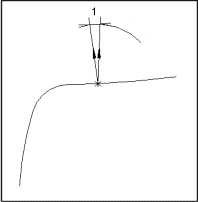
1. TOL
2. TOL
When verifying position continuity, GeomIntegrityCHECK reports discontinuities in curve and curve-segment transition points that exceed the TOL1 configuration tolerance. Such errors can cause problems in follow-up operations that build on the unity of curve paths, especially after scaling and transfer within a system environment of high accuracy.
Curves are checked for continuity in position, gradient, and curvature in relation to their segments. End and starting points of neighboring curve segments or curves are checked for sufficient distance with the aid of a 3-D intercept configuration tolerance TOL1. If the distance exceeds the tolerance, the curves are reported.
Recommended solution:
Insert a small fill piece, possibly a tiny element, in the gap that makes the discontinuity too large.
◦ In surfaces:
1. TOL
GeomIntegrityCHECK checks individual bounded surfaces and their segments for continuity in position, gradient, and curvature at several points. It reports discontinuities.
Recommended solution:
Regenerate the surfaces using the correct fundamental conditions.
◦ In topologies:
1. TOL
GeomIntegrityCHECK checks at several points the parity of two common boundary curves. If the gap between the curves exceeds the TOL1 gap configuration tolerance, GeomIntegrityCHECK reports the affected face boundary.
Bounded surfaces and their associated formations describe the surfaces of component parts and operation equipment. For this reason, the continuity of the bounded face has a special significance.
Position continuity, that is, continuous transition of bounded surfaces within a topology, is the most important quality characteristic within any surface group. A permissible discontinuity that is within the bounds of the tolerance can lead to a loss of the topology in the case of a change in the system or in the range of tolerances. It can also cause some systems to perform an automatic correction (healing). Because of this, unintentional changes, or new tiny elements, can occur.
Tangential or curvature discontinuity can have an effect on the surface quality or on the ability to mill the object.
Recommended solution:
In the case of gaps in face transitions, regenerate the affected faces with common boundary curves.
|  To determine the continuity of a structure created from bounded surfaces, the topological association of these surfaces must be established, in case this has not been fulfilled through topology elements. |
Neighboring bounded surfaces, which together form a particular part or complete surface of an object, are called composite surfaces, surface groups, or topology. Within a topology, special requirements apply regarding the faces in the boundary curves.
• Tangential Continuity
◦ In wire geometry (default check setting: < 0.1°):
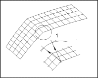
1. W_TOL
Tangential continuity means kink-free transition of two curves without a change in the tangential angle. A tangential discontinuity is generally visible and can be felt. Tangential discontinuities may be necessary in chamfers, bevels, and character lines, but in other types of models they are usually considered errors.
GeomIntegrityCHECK reports the curve segments or curves whose tangential angles exceed the TOL2 configuration angle value.
Recommended solution:
Interactively correct the curves by recreating them with identical tangent conditions or by rounding them with an additional curve with suitable tangent specifications. For example, round off two straights with a radius.
◦ In surfaces:
1. W_TOL
GeomIntegrityCHECK measures and compares tangential angles of two segments along a common border. If the maximum difference among the angles exceeds the configuration angle tolerance TOL2, the affected segment boundary is reported.
◦ In topologies:
The tangency angle or normal angles of two faces in a common boundary curve are checked at several points. If the angle difference exceeds the configuration angle tolerance TOL2, GeomIntegrityCHECK reports the affected boundary curve.
• Curvature Continuity
◦ In wire geometry (default check setting: < 10%):
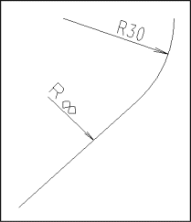
GeomIntegrityCHECK measures the curvature radii in curves and curve segments. It reports the curves and curve segments where the relative difference of the radii exceeds the configuration curvature tolerance TOL3.
Curvature continuity means parity of the curvature radius at the contact point with the curve and the resultant smooth curvature transition between two curves. Curvature continuity of curves is usually required only in parts with special functions, such as cams and worms, or due to stylistic elements.
Recommended solution:
Replace the faulty elements with elements that have suitable curvature conditions at each end. For example, elements with constant curvatures, such as straight lines and circles, should be replaced with free-form curves.
◦ In surfaces:
GeomIntegrityCHECK checks the curvature radii of two segments at several points along the common border. If the maximum relative curvature difference is greater than the configuration curvature tolerance TOL3, the affected segment boundary is reported.
◦ In topologies:
GeomIntegrityCHECK checks the curvature radii of two faces at several points in a common boundary curve. If the relative curvature difference exceeds the configuration curvature tolerance TOL3, the affected boundary curve is reported.
• Polynomial Degree
◦ In wire geometry (default check setting: < 11°):
GeomIntegrityCHECK reports the curves whose polynomial degrees exceed the upper limit specified in your configuration file.
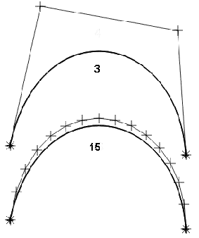
The degree of the polynomial depiction of a curve segment determines the degree of variance of that curve. The higher the degree, the greater the complexity of the curve.
Curves with high polynomial degrees are susceptible to unwanted curvature. Therefore, where appropriate, such curves must be approximated within the bounds of a tolerance when imported from or exported to another CAD system.
Recommended solution:
Avoid polynomial degrees greater than 9°. Practical experience has shown that polynomial degrees of up to 6° have proved to be the best. Unnecessary curves must be subdivided carefully into curves with lower degrees.
◦ In surfaces:
GeomIntegrityCHECK reports the surfaces where the polynomial degree in at least one parameter direction exceeds the upper limit specified in your configuration file.
A polynomial degree that is too high can lead to oscillations or, in the case of a reduction of the degree through approximation, to deterioration of the data quality with respect to faithfulness of form, storage requirements, and continuity.
Recommended solution:
Avoid polynomial degrees greater than 9°. Practical experience has shown that polynomial degrees of up to 6° have proved to be the best. Unnecessary curves should be subdivided carefully into curves with lower degrees.
◦ In drawings:
GeomIntegrityCHECK reports the curves whose polynomial degree exceeds the upper limit specified in your configuration file.
Curves with high polynomial degrees must be approximated during a transfer to another CAD system, that is, they must be approximated within the bounds of the configured tolerance and subdivided. If it is the case that the receiving system is only able to process curves with a particular maximum polynomial degree, it is possible that these curves could be falsely interpreted or ignored.
Recommended solution:
Compare the polynomial degree of curves with the given maximum value and, if appropriate, approximate through a curve of lesser degree, but with more segments, considering the specified tolerance.
• Waviness (default check setting: waviness is not allowed in a model; see the following definition):
◦ In wire geometry:
The waviness of a planar curve is checked through the number of sign changes along the curvature of the visible range of the curve.
A curve is rated as wavy if the sign changes more than once within a single segment or more than twice within a triple segment. The change of signs in the curvature should be taken into account only if the sum of the curvature on both sides of the change of signs is larger than a variable lower limit.
◦ In surfaces:
GeomIntegrityCHECK checks the waviness of a bounded surface by examining the number of sign changes along the length of the isoparameter lines u=u1 to u=un and v=v1 to v=vm.
A face with more than three sign changes along the total length of a parametric line or with more than one sign change within one of its segments is rated wavy. The frequency of sign changes is taken into account only if the curvature on both sides of a sign change is larger than a variable lower limit.
Recommended solution:
Regenerate the surface with correct fundamental conditions, such as the degree, edge curves, or restart points.
• Knot Distance
◦ In wire geometry (default check setting: > 0.02):
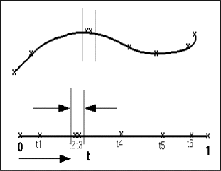
GeomIntegrityCHECK examines the knot vectors of NURBS curves for pairs of identical knots within the variable tolerance.
A knot vector is required for the definition of NURBS and B-Spline curves. The vector defines, among other things, the number of curve segments and the continuity of transitions between the individual curve segments.
The vectors are defined through a series of real numbers. Individual knots can be positioned on top of one another, known as multiple weighting of knots or multiple knots.
Recommended solution:
Regenerate the curves with large enough knot clearances.
◦ In surfaces:
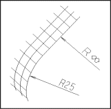
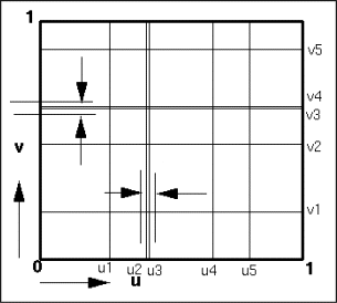
As is the case with NURBS and B-Spline curves, a knot vector for every parameter direction is required for the definition of NURBS and B-Spline faces. These define the number of face segments in the u and v parameter directions and the continuity of transitions between themselves. The knot vector is defined through a series of real numbers.
After a transfer of knots to a system environment with coarser tolerances, it is possible that neighboring knots can be identical in this new environment and, consequently, the internal continuity within the face can become undesirable.
After you have determined all the settings for the All Geom Type checks, click OK to start the checking process, or click Cancel to specify new settings.
