Refining the Dimension Loop, Tolerance Types, and Tolerance Values
After you define the part loop, the dimensions between all the selected features on the parts appear. The preliminary stackup analysis table is created. The next step is to review the dimensions and tolerances for each of the parts and ensure that they match with the actual, or required, dimensioning scheme of the part.
The initial dimensions represent the optimal dimensioning scheme to minimize variation of the stackup. You can add a feature to include additional dimensions existing on the drawing. Addition of a feature adds to the variation to the stackup results.
In the Stackups Details table, you can perform operations on any part, irrespective of the order. However, it is recommended to modify the parts sequentially, from top to bottom. Point to any row in the table to highlight that in the graphics window.
To Change Names of Features and Dimensions
• In the Stackup Details table, double-click the name and type a new name.
|
|
 In most cases, only the dimensions between features are included in the report unless the size of the feature contributes to the stackup results. |
To Change Tolerance Types
The default tolerance type is ± symmetric.
1. Right-click the icon indicating the type. A list opens.
2. Select the type.
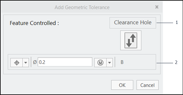
To Add Geometric Tolerance
1. Right-click the icon indicating the type. A list opens.
2. Select Geometric Tolerance. The Add Geometric Tolerance dialog box opens.
|
|
You cannot select geometric tolerances for edges, vertices, or points.
|
1. A feature that the Feature Control Frame controls
2. Datum Feature
3. Click

to swap the datum feature and the controlled feature.
4. In the Feature Control Frame (FCF), click the arrow next to the geometric characteristic. A list opens.
5. Select the characteristic.
6. Specify the tolerance value in the box.
7. If required, click the material modifier, and then select the modifier from the list.
8. Click OK.
| You can edit the tolerance value in the Stackup Details table, however, to edit the geometric tolerance definition, use the Add Geometric Tolerance dialog box. |