Defining Electric Nets
Electric nets are sets of conductive parts that carry the same electric potential. CCX initially combines all the adjacent conductive components into common nets.
When the initially detected nets consist of multiple parts, the nets are assigned a default name, for example Neti* and are listed under Potential-Free. If an initially detected net consists of a single part, it is assigned the name of the corresponding part.
Each net must be assigned one of the following net types:
|
Net Type
|
Description
|
|
Potential
|
The net is supplied with an electric potential. Such a net can act as source or target of a creepage or clearance path. It can also be assigned a voltage value, that you can use in a standard table for the analysis parameters. If custom parameters are used, the voltage value can be ignored.
|
|
Grounded
|
The net is explicitly grounded and can act as target of an analysis. Such a net automatically receives a voltage value of 0.
|
|
Potential-Free
|
The net is neither supplied with an electric potential nor is it grounded, for example screws. Such a net can act as an intermediate source and foreshorten a path. Nets from this list will not appear as source or target in the analysis.
|
You can perform the following operations on the selected net:
• Rename – To rename a net, right-click the net and select Rename.
• Show Content – To view the list of parts a net, right-click the net and select Show Content.
• Zoom to Net – To view the net closely, right-click the net and click Zoom to Net.
To Define Net Types
• On the Electric Nets tab, under Potential-Free, right-click a net and select Set Potential. The net is moved under the Potential list and you can set the value for the voltage.
• Under Potential-Free, right-click the net and click Set Grounded. The net is moved under the Grounded list and automatically assigned 0 voltage.
|
|
 You can select nets in the graphics window by selecting a surface that belongs to the desired net. CCX automatically detects the corresponding net from the selected surface. If the surfaces do not belong to a net, such as insulating surfaces, the options for setting potential are not available on the shortcut menu. To view a list of components of a net, right-click the net, and select Show Content.
|
The following table summarizes the properties of the net types:
|
Property
|
Potential
|
Grounded
|
Potential-Free
|
|
Selectable as source
|
|
|
|
|
Appears in the target list of a source
|
|
|
|
|
Can act as intermediate source to foreshorten a path between other nets
|
|
|
|
You should specify at least two nets of type Potential or one net of type Potential and the other as Grounded, so that a source-target pair exists.
Individual parameters are permanently erased after combining the nets. Therefore, you must assign the name and the type of part after manually combining the nets.
To Combine Individual Nets into a Common Net
In some cases, you must combine nets of relatively less significance into a common net. This is the case when the nets of relatively less significance have the same electric potential although there is no conductive connection between them in the model. You can manually or automatically combine the nets using a distance threshold.
Manually Merging Nets
To manually merge nets, select nets from the net list, right-click, and select Merge Selected Nets. The text color of merged net changes to blue. You can only combine nets of the same kind.
To separate the selected merged nets, right-click the merged net and select Reset Selected Nets.
Automatic Merging of Nets
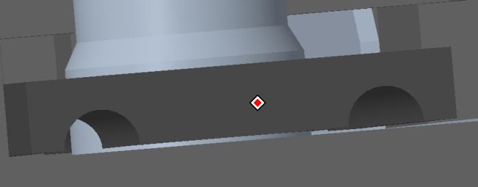
The automatic initialization of nets combines conductive parts that are directly adjacent. In some cases, a threshold may be required. This requirement may occur when components are modeled with a slight gap. See the example below:
To automatically merge nets within a certain proximity, specify a proximity threshold in the Auto merge distance box and click Auto Merge Nets.
Importing Nets from a Microsoft Spreadsheet
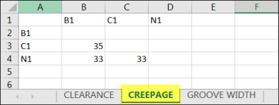
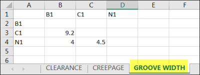
Use the Import Nets from Spreadsheet option to automatically import nets from a spreadsheet (.xlsx). The spreadsheet contains the creepage, clearance, and groove width values for each pair of n nets in an n x n table.
You can use this option in place of manually entering the creepage, clearance, and groove width values.
Rename the parts to include the underscore “_” and the corresponding net name from the spreadsheet. This helps to map the net to the model part from the spreadsheet.
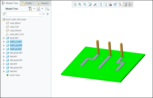
In this example, the parts are renamed to correspond with the nets in the spreadsheet, as follows:
• PART_B1 corresponds with net B1.
• PART_C1 corresponds with net C1.
• PART_N1 corresponds with net N1.
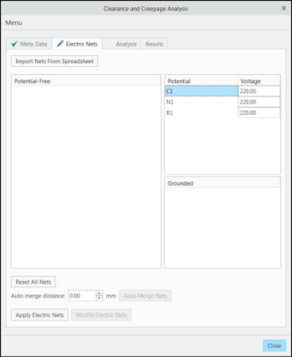
The net names C1, N1, and B1 that are specified in the spreadsheet exist in one of the parts of the model. When the net values are imported, the corresponding nets are generated and all parts belonging to the net are assigned to the respective net.
In this case, for Part_C1.prt, all the corresponding parts are assigned to net C1. As these parts are conductive, they are automatically added to the respective nets.
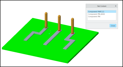
Right-click a net and click Show Content to view all the conductive parts associated with a net.
Perform the following steps to directly import the net parameters from a spreadsheet:
1. Click Import Nets from Spreadsheet. The Open dialog box opens which contains a list of spreadsheets (.xlsx files).
2. Double-click to select the spreadsheet that you want to import.
3. Select the .xlsx file that you want to import. The names of the nets are extracted from the spreadsheet and automatically assigned to the respective components in the model.
| The nets that are defined in the spreadsheet are automatically assigned the type Potential. |
4. You can edit the voltage values for the nets.
5. Click Apply Electric Nets.
6. On the
Analysis tab, click

.
The creepage, clearance, and groove width values for the nets are imported from the spreadsheet into the CCX net definition. The values are applied to all corresponding net pairs.
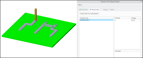
Two or more conductive parts connected by another conductive part (bridging it) causes a short-circuit and causes a conflict. The following figure shows an example of a short-circuit:
The conflicting nets are displayed under Potential-Free nets. Select a conflicting net, right-click, and click Show Content to view the parts.