To Specify the Projected Tolerance Zone
Click
Annotate >
 Geometric Tolerance
. The
Geometric Tolerance ribbon tab opens.
Using the Symbols command, you can specify the projected tolerance zone for GTOLs of the following types: angularity, perpendicularity, parallelism, and position.
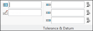
You can specify the values of the tolerance zone using the text boxes in the Tolerance & Datum group.
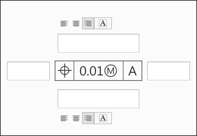
The string describing the projected tolerance zone is formed and assigned to the geometric tolerance in the graphics window. To enter symbols to the string, use the symbols in the Symbols group. The following is an example of a string in the following figure.
| • The values entered in the Tolerance & Datum group text boxes, can only form a string. • If you try to enter a string that is not valid, a warning message is displayed and the values in the text box is highlighted. |
To add values to the string in the following ways, use the text boxes in the Additional Text group:
• Text above the string
• Text below the string
• Text on the right
• Text on the left
• Prefix
• Suffix
 Geometric Tolerance. The Geometric Tolerance ribbon tab opens.
 Geometric Tolerance. The Geometric Tolerance ribbon tab opens.
 Geometric Tolerance. The Geometric Tolerance ribbon tab opens.

