Counterbore Options (ISO)
There are two common approaches to constraining
counterbored holes in accordance with ISO 1101:2012 and its companion standards.
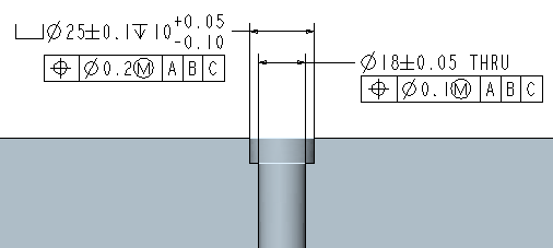
Different from hole
With this option, different positional tolerances are used to constrain the hole and the counterbore, as shown below:
In this case, the positional tolerances define separate coaxial tolerance zones for the hole and for the counterbore. Since the location of the counterbore is typically not as critical as the location of the hole, this method allows you to specify a larger value for the counterbore position tolerance.
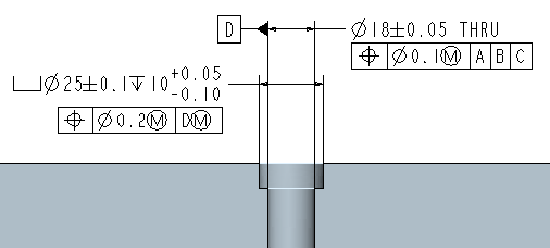
Relative to hole
With this option, a position tolerance is used to constrain the hole and another is used to constrain the counterbore relative to the hole, as shown below:
In this case, the hole is automatically set as a datum feature and the counterbore is constrained with a positional tolerance that references the datum established by the hole. This method typically communicates the design intent for a counterbored hole the better than the 'Different from hole' option described above because the location of the counterbore relative to the hole is typically the most important design consideration for counterbore features.
When the counterbored hole is a member of a pattern, each hole in the pattern is individually considered a datum feature with the specified datum feature label and the positional tolerance specified for the counterbore is intended to be relative to its corresponding hole. This is communicated by adding an Nx INDIVIDUALLY notation to the datum feature label and to the positional tolerance for the counterbore.