To Define Depth
All Hole Sets (except for Countersink and Web drilling), require specifying the drill depth type. To define the depth type and references use the Holes collector on the Reference tab. Alternatively, click Details and select Depth in the Holes dialog box that opens. Select one of the following hole depth icons to specify the depth or surface for drilling:
• 
—Drill from the start surface to specified depth. Specify the Start and End surfaces. If you select the checkbox next to the
Use breakout distance option, the system adds the BREAKOUT_DISTANCE parameter value when calculating depth.
For geometry hole sets, select

to specify the start surface to for drilling.
• 
(
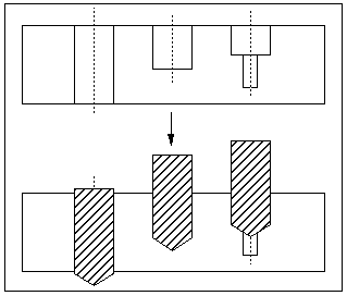
Auto)—Depth of drilling is determined automatically, by referencing hole geometry. If the selected axis is associated with several coaxial hole features, the maximum depth will be selected as long as the tool fits inside the hole diameter.
|  The Auto option is not applicable for geometry hole sets. |
• 
(
Through All)—Drill a through hole, from the retract surface all the way through the workpiece(s) or reference part(s) that the hole intersects. By default, all the reference parts and workpieces are used for depth calculation. You can unselect some of the parts or explicitly select parts, by using the
Models collector of the
Options tab in the
Holes dialog box. The
All Models option selects all the reference parts and workpieces.
• 
—Drill from the start surface to the depth of the selected reference. Surfaces and datum planes are selected by default.
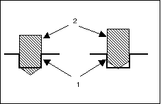
The Tool Depth option buttons, By Shoulder and By Tip, available for Blind and Auto drilling, determine if the drilling depth will be with reference to the shoulder or the tip of the tool. In the following illustration, the picture on the left shows drilling using By Shoulder, and the picture on the right shows drilling using By Tip. In both pictures, 1 indicates the outline of the hole being drilled and 2 indicates the outline of the tool at the final drilling depth.
 —Drill from the start surface to specified depth. Specify the Start and End surfaces. If you select the checkbox next to the Use breakout distance option, the system adds the BREAKOUT_DISTANCE parameter value when calculating depth.
 —Drill from the start surface to specified depth. Specify the Start and End surfaces. If you select the checkbox next to the Use breakout distance option, the system adds the BREAKOUT_DISTANCE parameter value when calculating depth.
 (
(
 (
(
