Specifying Approach Walls
For Volume milling, the tool is supposed to always be inside the milling volume. In some cases, however, you may want to perform cutting by the side of the tool only, that is, to make tool plunge outside the material. The Approach Walls Surfaces option on the References tab allows you to select side surfaces of a mill volume that can be violated during tool approach and exit. The user interface for selecting these surfaces is the same as for other types of surface selection in Milling.
If a Mill Window is used, then you will be prompted to select entities from the window curve (that is, the window outline in the start plane) rather than surfaces from the Mill Volume. Selected entities will be used as sides of the tool approach.
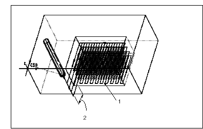
If Approach Walls have been defined, the system will attempt to make an approach and exit for every slice through these walls and plunge outside material, as shown in the following illustration. The length of approach/exit extension is defined by the APPR_EXIT_EXT parameter plus tool radius.
If the Approach Walls have been specified, the datum point, axis, or sketch used for approach or exit in Build Cut can be outside the milling volume.
Profiling passes will not be created along the surfaces selected as Approach Walls.
The following illustration shows specifying Approach Walls for Volume milling.
1. Select this wall of the volume using the Appr Walls option
2. APPR_EXIT_EXT + CUTTER/DIAM / 2

