Sketching a Turn Profile
When sketching a Turn Profile, keep in mind that the sketch must lie in the XZ plane of the NC Sequence coordinate system and completely on one side of the x-axis (either positive or negative).
The default orientation of the model upon entering Sketcher is as follows:
• If the workcell is defined as Horizontal—with the z-axis pointing to the right and x-axis pointing up.
• If the workcell is defined as Vertical—with the z-axis pointing up and x-axis pointing to the right.
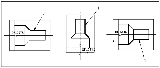
However, you can sketch in any view orientation of the model provided the XZ plane is parallel to the screen and the sketch is completely on one side of the NC Sequence x-axis.
The following illustration shows sketching the cut in various view orientations.
1. Section sketch
To define a Turn Profile by sketching, click

on the Turn Profile dashboard:
• For Thread turning, sketch the first tool movement, which corresponds to the major diameter for an external thread and to the minor diameter for an internal thread.
The sketch must be on continuous chain of entities, and the entities should not form a closed loop.
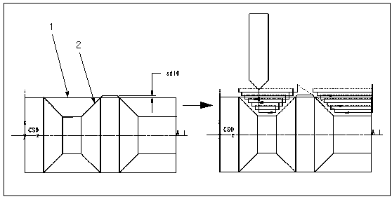
1. Workpiece boundary
2. Section sketch


 on the Turn Profile dashboard: