Example: Manufacturing Criteria Name Usage while Placing a UDF
The following example illustrates the usage of manufacturing criteria while placing a user defined feature (UDF).
Setting Up the Configuration Option
This manufacturing criteria usage in the process table is driven by the udf_mfg_info_setup_file configuration option. You must set up this configuration option to point to a file with a .xml extension. This file stores the UDF-manufacturing criteria name mappings.
Defining Manufacturing Criteria Names (Creo NC)
After setting up the udf_mfg_info_setup_fileconfiguration option, you must define the manufacturing criteria name.
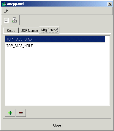
Click Tools > Mfg Criteria – UDF Files Setup in the Manufacturing Process Table. A dialog box opens. The name of this dialog box is the value that you have specified for the mfg_udf_info_setup_file configuration option. In this example, the value for the mfg_udf_info_setup_file configuration option is C:\Creo\ancpp.xml. Enter the manufacturing criteria names as shown in the figure below.
Save the changes by clicking

and click
Close.
Creating a UDF
1. Select the reference model on the Model Tree and click Open on the shortcut menu. The reference model opens in the Part mode.
2. Click Tools > UDF Library and click Create on the Menu Manager.
3. Type the name of the UDF as
dia5_generic. Click

. The
UDF dialog box opens and the
UDF OPTIONS menu appears.
4. Click Standalone and Done on the UDF OPTIONS menu. The UDF FEATS and SELECT FEAT menus appear.
5. To specify the contents of the UDF, you must select a hole (Hole id 5298) and the annotation feature (Annotation 1) that includes the hole. The selected hole and annotation feature are highlighted in the model, as shown below.
6. Click OK and Done on the SELECT FEAT menu.
7. Click Done/Return on the UDF FEATS menu.
8. Specify the reference prompts to be displayed while placing the UDF. After specifying all the required prompts, the MOD PROMPT and SET PROMPT menus appear.
9. Click Done/Return on the SET PROMPT menu.
The UDF is saved in the working directory. The UDF file has a .gph extension.
Adding the UDF to the Mfg Criteria–UDF Files Setup Dialog Box
Switch to
Creo NC by selecting the manufacturing model on the
Window menu. Open the Process Manager. Click
Tools >
Mfg Criteria – UDF Files Setup. The
Mfg Criteria – UDF Files Setup dialog box opens. Click the
UDF Names tabbed page. To add a UDF to the list of UDFs, click

. Browse and select the UDF file that you created (
dia5_generic) and click
OK. The UDF file name is added to the list of UDF names as shown in the figure below.
Mapping the UDF Name to One or More Manufacturing Criteria Names
In the
Mfg Criteria – UDF Files Setup dialog box, click the
Setup tabbed page. Select the manufacturing criteria names (
TOP_FACE_DIA5) that you want to associate with the selected UDF from the
Not Selected Criteria list and click

. The manufacturing criteria names are added to the
Selected Criteria list as shown in the figure below. Save the changes by clicking

and click
Close.
Placing the UDF
Select the reference model on the Model Tree and click Insert > User-Defined Feature. You are prompted to select the UDF file that you want to insert. Browse and select the dia5_generic.gph file and click Open.
The Insert User-Defined Feature dialog box opens. Clear theMake features dependent on dimensions of UDF check box and click the Advanced reference configuration check box. Click OK.
The
User Defined Feature Placement dialog box opens. On the
Placement tabbed page, select the references that you specified while defining the UDF and select the reference on the Model Tree or in the graphics window. Click

.
The DIA5_GENERIC dialog box opens. The name of the dialog box is the same as the name of the UDF that you want to place.
Select TOP_FACE_DIA5 as the manufacturing criteria and click OK. The UDF group is created and added to the Model Tree. Click on the UDF group to expand it. The hole (Hole id 5298) and the annotation feature (Annotation 1) that you specified while creating the UDF are part of the UDF group. You can edit the annotation feature to confirm that the manufacturing criteria used by the annotation feature has been updated to TOP_FACE_DIA5.


 and click Close.
 . The UDF dialog box opens and the UDF OPTIONS menu appears.
 . Browse and select the UDF file that you created (dia5_generic) and click OK. The UDF file name is added to the list of UDF names as shown in the figure below.
 . The manufacturing criteria names are added to the Selected Criteria list as shown in the figure below. Save the changes by clicking
  and click Close.
 .
.