Example: 2-Axis Trajectory Milling
In this example, you are going to use a chain of edges as the final tool trajectory. You can select the model edges directly as machining references. However, in this example a sketched curve based on these edges is created asynchronously. You can also define such a Curve feature prior to creating the NC sequence. In either case, if geometry of the edges changes at a later time, the Curve feature geometry and the tool trajectory will change accordingly.
You will also set the NC sequence parameters so as to define multiple cutting passes for the NC sequence.
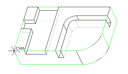
The manufacturing model is shown in the following illustration. You are going to machine the slot on the right.
1. Create a 2-axis Trajectory milling NC sequence.
2. Select a flat end mill with cutter diameter equal to the width of the slot. Set the manufacturing parameters as follows:
NUMBER_LAST_FINPASSES 2
NUMBER_FIRST_FINPASSES 1
LAST_FINPASS_OFFSET 0.1
FIRST_FINPASS_OFFSET 0.5
NUMBER_LAST_FINCUTS 1
NUMBER_FIRST_FINCUTS 0
3. To define the trajectory curve asynchronously, on the
Curve Trajectory tab, click
Datum >

. The
Sketch dialog box opens.
4. Select the bottom of the slot as the sketching plane. The Sketcher tab opens.
5. Click
 Use
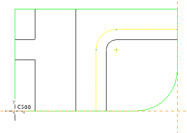
Use and select the three edges shown in yellow in the next figure. Click

to exit Sketcher.

6. On the
Trajectory Curve tab, click

to resume the process of creating the trajectory milling sequence.
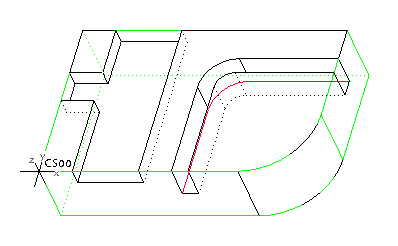
7. On the References tab, click Select and select the curve you just created (shown in red in the following figure) as the Machining Reference. Click Done.
8. Select the Offset Cut check box to specify an offset for the cut motion.
9. Click
 Material To Remove
 to flip the material removal side from one side of the reference curve or sketch to the other.
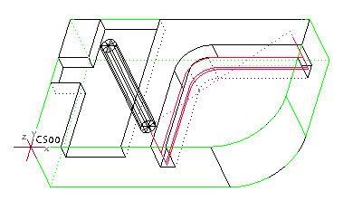
The completed toolpath is shown in the following illustration.
10. Click

to save the changes.


 . The Sketch dialog box opens.
 Use and select the three edges shown in yellow in the next figure. Click
  to exit Sketcher.
 to resume the process of creating the trajectory milling sequence.
 Material To Remove to flip the material removal side from one side of the reference curve or sketch to the other.
 to save the changes.