Using the Chamfering Tool
You can use a tool of the type Chamfering to machine a Top Chamfer feature.
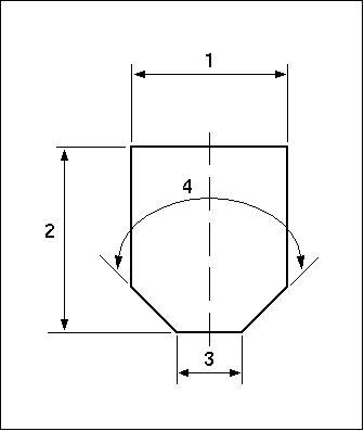
The parameters of a Chamfering tool (as shown in the following illustration) are:
1. Cutter Diameter
2. Length
3. Point Diameter
4. Point Angle
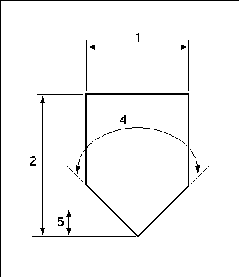
By default, the Point Diameter is equal to 0, and the tool section looks as shown in the following illustration. Instead of assigning a value to Point Diameter, you can specify a value for Gauge Offset (5). This value does not affect the tool section display, but it will be reflected in the tool path computation.
If the tool is big enough to completely machine the chamfer in one pass, it is symmetrically located with respect to the chamfer. That is, the distance between the top cutting edge of the tool and the top edge of the chamfer is the same as the distance between the bottom edge of the chamfer and the bottom cutting edge of the tool.
If the chamfer is too big to be machined in one pass, you can control the number and location of passes by using the Tool Overlap options located on the Cut Control tabbed page of the Tool Path Properties dialog box:
• From Tool—The tool overlap equals the Axial Depth value, retrieved from the cutting data stored with the tool. This option is available only if the tool contains associated cutting data.
• Enter—Type the value of tool overlap in the text box to the right.
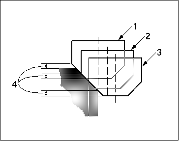
The tool positions are shown in the following illustration. On the first (1) and all the intermediate (2) passes, the top cutting edge of the tool is above the top of material to be cut by a vertical distance of tool overlap (4). On the last pass (3), the bottom cutting edge of the tool is below the bottom edge of the chamfer by the same distance of tool overlap.


