Example: Creating a Top Chamfer Feature
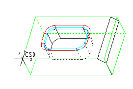
The model in this example has two Top Chamfer features: one consists of a single chamfered edge, open on both ends, and the other is a closed loop of chamfered edges located on top of a pocket.
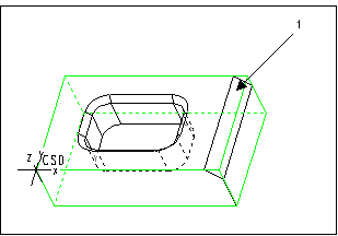
1. To create the first Top Chamfer feature, select the surface of the chamfer (1) as the Floor surface.
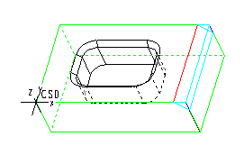
The system creates the Top Chamfer feature, as shown in the following illustration.
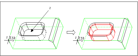
2. To define the second Top Chamfer feature correctly, you have to create the Pocket feature first, as shown in the following illustration. Select the bottom of the pocket (2) as the Floor surface.
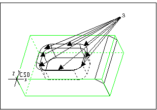
3. Create the second Top Chamfer feature and select all the chamfered surfaces surrounding the pocket (3) as the Floor surfaces, as shown in the following illustration.
The system creates the Top Chamfer feature, as shown in the following illustration.
