Example: Verifying a Dimension Tolerance
You can use the CMM model or a drawing of the reference part to select the dimension to verify.
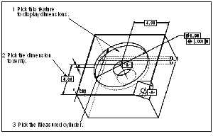
The following example shows verifying a dimension tolerance using the CMM model.
To verify a dimension tolerance as shown above:
1. Click
Inspect >
 Verify
. The TOLERANCE menu appears.
2. When defining the Tolerance element, choose CurrentModel from the TOLERANCE menu, and pick the big circular cut. The system displays dimensions associated with the selected feature.
3. Pick the dimension you want to verify.
4. Choose Along Y from the DIM/CORTOL menu.
5. Define the Features element. Pick the Measured cylinder.
6. Press OK to create the Verify step.
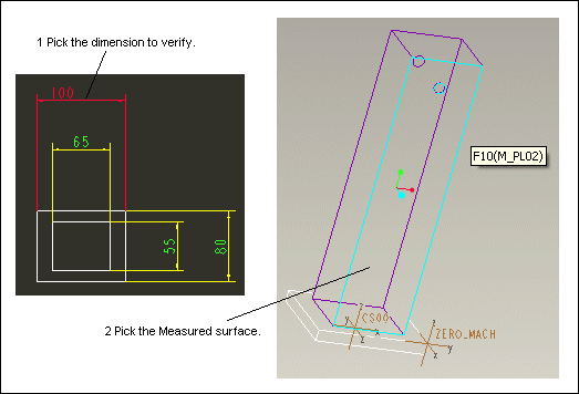
The following example shows verifying a dimension tolerance from a drawing.
To verify a dimension tolerance as shown above:
1. Click
Inspect >
 Verify
. The TOLERANCE menu appears.
2. Choose From Drawing from the TOLERANCE menu. The system prompts you to enter the name of the drawing; entering a question mark (?) opens the browser to let you search for the drawing.
3. Pick the dimension you want to verify.
4. Choose Along X from the DIM/CORTOL menu.
5. Define the Features element. Pick the Measured surface.
6. Press OK to create the Verify step.


 Verify. The TOLERANCE menu appears.
 Verify. The TOLERANCE menu appears.