|
|
|
|
|
|
|
|
|
|
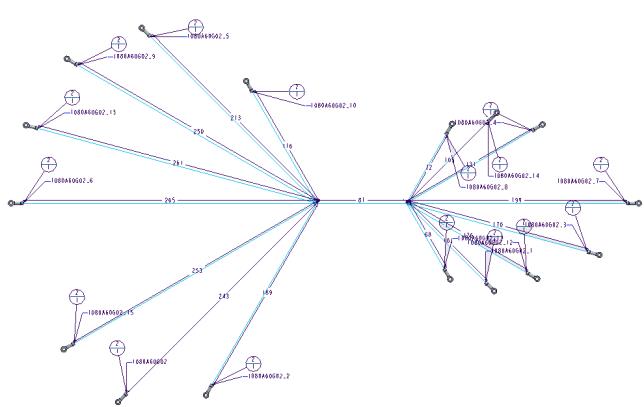
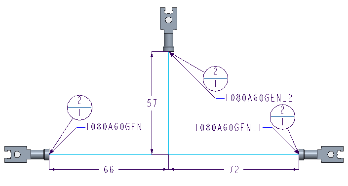
Cone angle 0 degrees
|
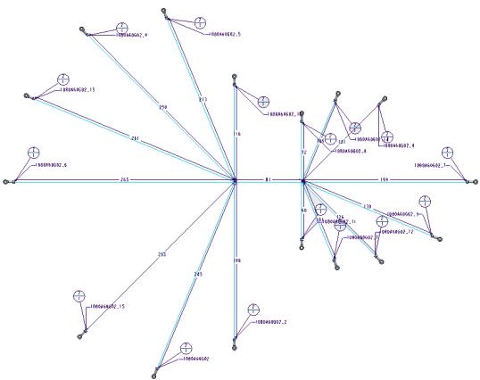
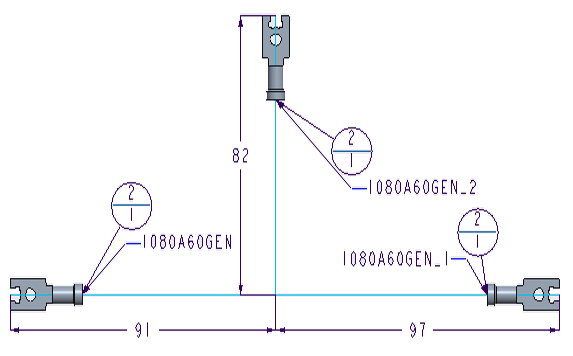
Cone angle 30 degrees
|
 |
 |
|
Key Parameter Name
|
Description
|
Default value
|
|
Log File
|
Controls the creation of log files.
|
No
|
|
BOM File
|
Controls the creations of BOM files.
|
Yes
|
|
Wire List File
|
Controls the creation of Wire List files.
|
Yes
|
|
Unique File Names
|
Controls the names of the created files.
|
No
|
|
Key Parameter Name
|
Description
|
Default value
|
Example
|
||
|
Extra Length (%)
|
Increases the value of the wire lengths displayed in the Wire List and BOM tables by the specified percentage.
Type a value that is a real number restricted to 3 decimals.
|
0
|
Extra Length (%) : 5.125
|
||
|
Fixed Length
|
Increases the value of the wire lengths displayed in the Wire List and BOM tables by the specified length.
Specify a whole number for metric or a real number to one decimal for inches. The units specified for Fixed Length must match the spools units.
If Fixed Length and Extra Length (%) are specified, the value of Fixed Length is used for calculating the change in the wire length.
|
0
|
Fixed Length : 5(mm) or 0.1 (inches)
|
||
|
Round to Length
|
Rounds up the value of the wire length displayed in the Wire List and associated spool in the BOM table by the specified length. Specify a whole number for metric or a real number that can have up to one decimal for inches.
|
0
|
Round to length : 5(mm) or 0.5 (inches)
|
||
|
Include Shields in Wire List
|
Controls the listing of shields in the Wire List table. If you select Yes, the shields that are fully routed appear in the generated Wire List table.
|
Yes
|
 Harness Mfg. The Harness Manufacturing Extension dialog box opens.
Dimension to Front is set to No | Dimension to Front is set to Yes |
 |  |
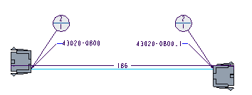
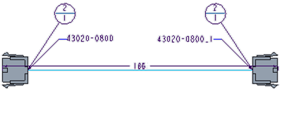
Shortest wire view | Centralised View |
 |  |
Empty pins not displayed | Empty pins displayed |