About Harness Manufacturing Drawing
The flattened harness drawing contains all the components of the 3D harness along with the following information:
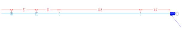
Harness dimensions
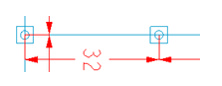
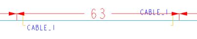
Each segment is annotated with its correct dimensions. A segment is the shortest wire length between the bundle ends, cosmetic features, and cable jackets. The following image shows the cosmetic features.
Cosmetic Feature | Cosmetic Feature Symbol |
Tie-wrap | |
Tape | |
Marker | |
Bundle Ends | |
Cable Ends | |
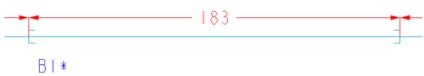
| • B1*is the bundle feature name. • CABLE_1 is the cable feature name. |
Bill of materials (BOM) table
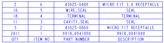
Comprises a list of raw materials, their part numbers, quantities, and a description for all the components in the harness. The BOM table appears on the bottom right side of the manufacturing drawing, with the table cell headings at the bottom. Although, the BOM table is automatically generated, you can edit the content. The following figure shows a BOM table.
Mapping Parameters—The model may contain parameters for the model description, connector seals, and spool part numbers. You can extract these parameters in the harness drawing by mapping the parameter name to the following options:
• Model “Description”
• Connector “Seal”
• Spool “Part number”
The model description parameter can be mapped to any standard model parameter. You can access the model parameters from the Parameters dialog box. Right-click a part name in the Model Tree and click Parameters to open the Parameters dialog box.
The connector seal parameter must be a logical cabling parameter. To assign the name of the connector seal parameter, do the following:
1. Select a connector from the Model Tree or Graphics window.
2. Click
 Cabling Parameters
 on the
Cabling tab. The
Electrical Parameters dialog box opens.
3. Identify a pin level parameter that you want to map to the seal name.
The spool part number parameter must be mapped to a spool parameter. To assign the name of the spool parameter, do the following:
1. Click
 Spool
Spool. The
SPOOLS menu opens.
2. Click Edit. The Select Spools dialog box opens.
3. Select a spool and click OK. The Electrical Parameters dialog box opens.
4. Identify the parameter that you want to map to the spool part number.
After you flatten the harness, the settings are saved, and are available the next time you open the Harness Manufacturing Extension dialog box.
| • The consolidated spool usage is the sum of all the wire lengths by part number, as defined in the Wire List. It also includes the internal lengths. • The unit of measure for spools is obtained from the (.spl) spool file. |
Wire List table
The Wire List table provides the connectivity information that includes the following:
• Wire name
• Spool name
• Wire length including any internal lengths
• Connector Reference Designator
• Cavity or pin number
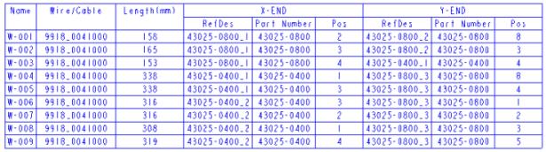
The Wire List table appears on the top left side of the manufacturing drawing. Although, the Wire List table is automatically generated, you can edit the content. If the Wire List is too large to be placed on the first sheet of a standard drawing sheet, it is placed on an additional sheet. The wire lengths mentioned in the Wire List table should be used for manufacturing the harness. The following figure shows a Wire List table.
|  The wire lengths approximates to the nearest millimeter or 0.1 inch. |
Connector Cavity table
A Connector Cavity table is generated for each connector and visible terminal present in the harness. This table lists the connector model name and reference designator. In addition, it also lists the following for each connector cavity:
• Terminal part number
• Seal part number
• Wire part number for each cavity or pin
The Connector Cavity tables appear on the right of the manufacturing drawing. On a variable drawing sheet, they appear adjacent to the 2D topographical representation. If the Cavity table is too large to be placed on the first sheet of a standard drawing sheet, it is placed on an additional sheet. If several wires terminate at a single connector cavity, the wires are listed under the cavity name. The visible terminal cavity tables list only the wires that are connected to the terminal. The following figure shows a Connector Cavity table.
| • The Connector Cavity tables are generated in the Standard and Advanced packages. • In the Advanced package, a rear view of the connector model is also displayed. |