Using Coordinate Systems
If you create your own component models, you must provide each one with a coordinate system that represents the part origin to the ECAD package, and that includes the height dimension along the z-axis. If you are creating the component as a custom part in Creo Parametric, start the part by placing the (0,0,0) of the coordinate system at the intersection of the three default datum planes.
As ECAD places components by locating component coordinate systems in relation to the board coordinate system, the coordinate system orientation you use for placement on the ECAD outline should match that of the custom Creo Parametric part. If the replacement is an assembly, an assembly coordinate system must be present. Incorrect orientation results in incorrect placement of the replacement component.
|
|
 When using a subassembly as a component the coordinate system used for placement in the subassembly must be created from 3 planes. The XY plane of this coordinate system must be parallel (mate) to the XY plane of the default coordinate system of this subassembly. |
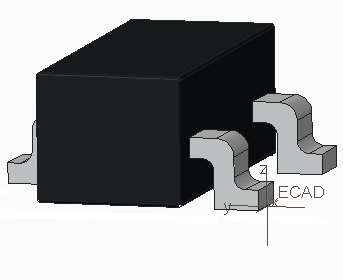
The illustration below shows a custom part, created in Creo Parametric, representing a DIP16 with the csys ECAD_DEFAULT located at the part origin (usually pin 1).
In IDF 3.0, the components can be placed using the Mate Offset assembly option. For all other formats, the system mates the components to the board.
You can create a section plane for the component outline as a cross section, or select a planar surface for the component outline. The section plane is used as the footprint of the extents of the part and must be parallel to the xy-plane of the placement coordinate system. You are prompted to identify the section plane as part of the export procedure.
Orient the component so that the z-axis of its chosen coordinate system points in the direction normal to the surface of the board, away from the surface:
• If you place a component on the top surface of the board, the direction of the z-axis of the component’s coordinate system points in the same direction as the z-axis of the board’s coordinate system.
• If you place a component on the bottom surface of the board, its z-axis points in the opposite direction from the board’s z-axis.
You should know how the default component coordinate systems on the parts in your ECAD package are positioned.
Top and Bottom Side
Creo Parametric uses the coordinate system to distinguish between top and bottom surfaces:
• The z-axis of the coordinate system of the board should be normal to the top and bottom planes.
• The positive z-axis should point from the bottom plane to the top plane.
• The bottom of the board should coincide with the xy-plane of the ecad csys.
You can select or create any coordinate system where the z-axis is normal to the top and bottom planes and the origin is located on either the top or the bottom surface of the board part.
| • Creo Parametric does not support left-handed coordinate systems. If used, component placement will not be as expected. • As the direction of the z-axis is normal to the top and bottom, and also points toward the top, the bottom and top can be different sides of the same surface. • When importing or exporting information that depends on the identification of the top and bottom surfaces of the board, the system checks to see if two parallel planes are normal to the z-axis. If so, it designates these the top and bottom based on the direction of the z-axis. • If more than two planes are normal to the z-axis, the system prompts you to select a top and a bottom. The bottom surface can be a surface or datum. The top can be: ◦ A surface or datum (if importing) ◦ A surface or datum with a cross-section on it (if exporting) |