ECAD to MCAD Workflow
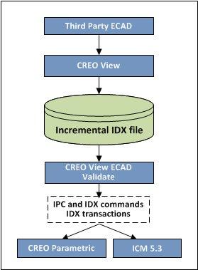
The following figure shows the sequence of the collaboration effort that begins in ECAD.
1. The ECAD user creates a new PCB design and places mechanical components in the native ECAD PCB Layout tool.
2. He saves the design as a baseline EDMD IDX file and sends it to the MCAD user.
3. The MCAD user opens the design and verifies the placement of mechanical components.
4. The ECAD and MCAD users agree on a baseline EDMD IDX file to begin the design process.
5. The ECAD user generates an incremental EDMD IDX file from within the native authoring tool.
6. The MCAD user accepts or rejects the proposed changes and updates the EDMD IDX file.
7. The MCAD user then sends this updated EDMD IDX file to the ECAD user.
8. The exchange continues until the designs are synchronized and a new EDMD IDX baseline file is created.

