About Merging Segments
You can merge two or more distinct pieces of unattached segments to form one segment. When merging segments, keep in mind the following points:
• Geometry from a first segment can only be a base segment.
• The segments must be tangent to one another.
• The driving and offset sides of the segments to merge are swapped automatically, if necessary, to match the sides of the earliest segment created.
|
|
 Swapping the driving and offset sides can change the location of cuts located on the segments. For example, when you reorder a Merge feature in the Model Tree and reinsert it before a cut that references an automatically swapped side, the location and the geometry of the removed material may change. |
• Icons in the lower right of the screen indicate whether a part has one or more distinct pieces of unattached segment geometry.
• You can also merge segments automatically during segment creation by clicking the Merge to model check box on the Options tab.
|
|
This option is available for Planar, Extrude, Revolve, Sweep, Offset, and Swept Blend segment tools.
|
|
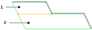
Unattached Tangent Segments
|
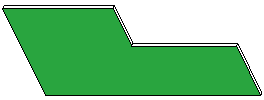
Merged Segment
|
|
|
1. Unattached segment.
2. Base segment to which the unattached segment is merged.
When you merge segments, you must define the following elements:
• Basic Refs—Select surfaces of the base segment.
• Merge Geoms—Select surfaces of one or more unattached flat segments to merge with the base segment.
• Merge Edges—(optional) Add or remove edges deleted by the merge.
• Keep Lines—(optional) Control the visibility of merged edges on surface joints.