About Bending Board Segments
Use the Bend tool to bend a board segment into an angled or rolled shape. You can add a bend to an existing segment at any time during the design process by defining a bend line as a reference point to create the bend geometry and to calculate the developed length. You can define bend settings during feature creation, or you can predefine them using board parameters or in the Bends area of the Preferences dialog box.
Types of bends:
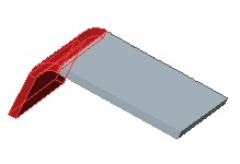
• Angled Bend—The bend is formed on one side of the bend line or equally on both sides.
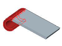
• Rolled Bend—The bend is defined by both the radius and the amount of flat material to bend.
|  When you create a rolled bend, keep in mind that the bend will fail if the material, rolled into a spiral, bends through itself. |
• Planar Bend—The bend is formed around an axis that is normal (perpendicular) to the driving surface and sketching plane.
Keep in mind the following points when adding bends to a design:
• A bend cannot cross another bend.
• You can unbend zero-radius bends.
• When you unbend and bend back a part, the developed length remains the same.