Workflow to Logically Designate Components and Route Cables
The workflow for designating the components and routing cables using logical information is as follows:
2. Auto Designate the connectors using logical data.Use the Auto Designator dialog box to select and match assembly components to connectors from the logical reference.
3. Route wires and cables using logical data.Use the Route Cables dialog box to route the selected wires or cables between their from and to connectors. The wires automatically follow the shortest path through the network.
Example
Refer the
cabling_assembly.asm sample assembly to learn how to logically designate components and auto route cables through them. Sample models are available at
<Creo load point>\Common Files\help\sample_models\cabling. Open the
cabling_assembly.asm. Select
LOGICAL_ROUTE from the
 Saved Orientations
 list. Set
LOGICAL_ROUTING as the working harness.
1. Click Import. The WIRELIST IMP menu appears.
2. Click Creo Schematics. The REF XML menu appears.
3. Click Whole XML. The File Open dialog box opens.
4. Double-click shield.xml to import the logical data.
5. Click Done in the WIRELIST IMP menu.
6. Click
 Auto Designate
. The
Auto Designator dialog box opens.
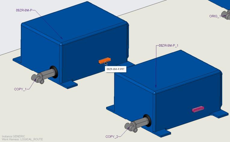
7. Click LOGICAL-1 and click the component as shown in the figure.
8. Click LOGICAL-2 and click the component shown in the figure.
9. Click OK.
10. Click
 Route Cables
 to open the
Route Cables dialog box.
11. Click

. The
Find Cables dialog box opens.
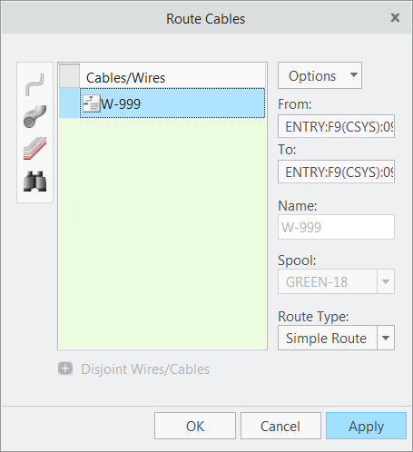
12. Click
W-999, click

to move it to the items selected list, and click
OK.
Note the from, to, spool, and route type information is filled from the logical data.
13. Click Apply. The wire is routed between the selected connectors.
14. Click Cancel to close the Route Cables dialog box.
15. Click Location. The Location tab opens.
16. Add locations as shown in the figure.
| Tip: Click  to flip the direction of progression along the selected segment. |