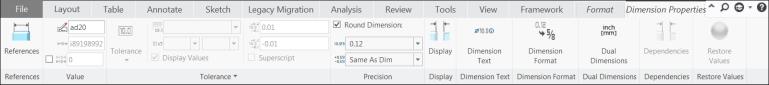
About the Dimension Ribbon Tab
The Dimension tab is a contextual ribbon tab that appears when you place a newly created dimension, or select an existing dimension. The Dimension ribbon tab lists properties of the selected dimension. You can use commands available under various groups to modify properties of the selected dimension.
Following groups are available in the Dimension ribbon tab:
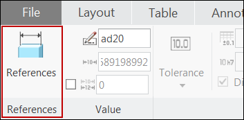
• References
The command in the Reference group allows you to control references that you used to create the selected dimension.
Click the Reference button. The References dialog box opens, listing details of references that were used to create the selected dimension. You can modify the existing references of the selected dimension.
|  The References button is disabled in Drawing mode. |
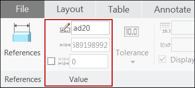
• Value
Commands in the Value group allow you to control the dimension name and its value.
The Name text box displays the symbolic name of the selected dimension. You can modify this symbolic name of the dimension.
The Nominal Value text box displays the nominal value of the selected dimension. You can modify the nominal value if you select a single or multiple driving dimensions.
The Override check box enables you to override the nominal value of the selected dimension. For driving dimensions, override value is disabled. If you select a single dimension and specify the Override Value, the override value appears as the dimension value in the graphics area.
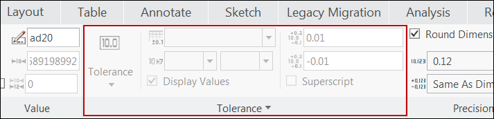
• Tolerance
Commands in the Tolerance group allow you to control the tolerances applied to the selected dimension.
The Tolerance button lists the tolerance modes that you can specify for the selected dimension. The Tolerance button is disabled by default. Set the value of the tol_display Detail option to yes to enable it. You can specify one of the following tolerance modes:
◦ Nominal — Displays either the nominal or override value of the dimension for both ANSI and ISO/DIN standards.
◦ Basic — Displays either the nominal or override value of the dimension surrounded by a rectangle for both ANSI and ISO/DIN standards.
| • For the Nominal and Basic tolerance modes, tolerance format details are disabled, and are not displayed along with the dimension. • You cannot set a dimension as basic and inspection at the same time. The Basic option under Tolerance group and Inspection option under Display group work as mutually exclusive options. |
◦ Limits — Displays the sum of dimension value and current value of upper and lower deviation respectively, as upper and lower limit for the dimension.
◦ Plus-Minus — Displays the dimension value accompanied by upper and lower tolerance deviation values.
◦ Symmetric — Displays the dimension value along with a single tolerance value that specifies equal upper and lower deviation.
| For the Limits, Plus-Minus, and Symmetric tolerance modes, • With the ANSI standard, all other tolerance format details (Tolerance Table, Class/Grade, Display Values are disabled). Upper and Lower Tolerance are enabled for Limits, Plus-Minus, and Symmetric modes. Superscript is enabled with the Symmetric mode only. • With the ISO/DIN standard, you can have the Tolerance Table options, as None, General, or Broken Edge, and further specify other tolerance format details. Additionally, for the Limits, Plus-Minus tolerance modes, the Shaft or Hole options are available when you load tolerance table containing shaft or hole tolerance. • The Superscript option is enabled only for the Symmetric tolerance mode. |
The Tolerance Value Only option enables you to display only the tolerance values instead of the dimension value for the selected dimension.
When you select multiple dimensions, the tolerance value and all the other tolerance format details appear empty.
| All the Tolerance group commands are disabled for reference dimension types, such as, reference dimension and ordinate reference dimensions. |
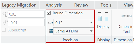
• Precision
Commands in the Precision group allow you to define the precision of the dimension value and tolerance value of the selected dimension.
The Round Dimension check box allows you to specify if rounding should be done when the dimension value is displayed. For driving dimensions, you can control the rounding of both decimal and fractional dimension format. However, for driven dimensions, you can control rounding of only decimal format. For driven dimensions with fractional format, the rounding is always done and you cannot cancel it.
| For driven dimensions, the rounding of dimension is just for display purpose, and the actual dimension value is not updated. Thus, rounding of un-rounded driving dimensions change its value and requires model regeneration. |
This group allows you to set the number of decimal places that the dimension value should appear rounded to. Creo allows maximum of 13 digits for the dimension value, that includes the integer and fractional portion of the value. A dimension can appear with, 13 less the number of integer digits in the dimension value, as the maximum number of decimal places.
For fractional value of the dimension, you can select a pre-defined denominator value for rounding, as 0, 1/2, 1/4, 1/8, 1/16, 1/32, 1/64, or 1/128.
Rounding of decimal and fractional formats of dimension tolerance value, work in the same way as that of rounding of dimension values.
| As tolerance value is not applicable for a reference dimension, the Precision option is disabled for reference dimension and ordinate reference dimensions. The default Same As Dim option appears for all such reference dimensions. |
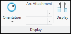
• Display
Commands in the Display group allow you to control the display of the dimension.
The
Orientation command allows you to specify the orientation of the selected dimension. When you click the
Orientation button, depending upon the type of dimension that you select, the list of corresponding orientation options appears. The
Orientation button is available only when you select a single dimension. For additional information on specifying orientation of dimensions, see
About Changing the Orientation of a DimensionOptions under Arc Attachment enables you to set the location of the attachment points for the linear dimension defined with an arc or circle as its references. You can set the attachment point only if the selected dimension is created with at least one of its references is defined using either a tangent point or center point on an arc, elliptical arc, circle or ellipse. You can set the attachment points for the dimension line on the selected reference as Min, Max, or Center, that is. as the minimal or maximum distance from the arc, or from center of the arc. Options under Arc Attachment are disabled for dimensions other than a linear dimension defined on an arc or a circle.
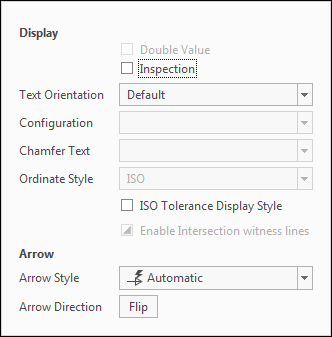
The Display option allows you to specify the text orientation and configuration for the selected dimension. Click the Display button. The Display panel appears with the following options that you can use to control the display of the selected dimension.
◦ Double Value — Enables you to display twice the actual value of the selected dimension. This option is available only for linear and angular dimension defined between two line entities. The dimension with double-value is identified by double arrow.
◦ Inspection — Displays the selected dimension as inspection, by enclosing the dimension value in an oval box.
| • The Inspection check box is disabled for linear reference dimension and ordinate reference dimension. • You cannot set the tolerance mode for a dimension as basic and display type as inspection at the same time. When the Basic option under Tolerance group is selected, the Inspection option is disabled, and vice versa. |
◦ Text Orientation — Enables you to set the orientation of the dimension text relative to the dimension line, as horizontal, parallel to and above or below the dimension leader.
◦ Configuration — Enables you to set the dimension configuration for the selected dimension. The available configurations depends upon the type of dimension that you select, as:
Linear dimension-Linear, and Center Leader
Diameter dimension-Linear, Center Leader, and Leader
Chamfer dimension-Linear, and Leader
For all other types of dimensions, this option is disabled.
◦ Chamfer Text — Enables you to define the format of the chamfer notification display for the selected chamfer dimension. You can set the notification display as, Default, Dx45, Cd, 45xD, Customized, or D.
◦ Ordinate Style — Enables you to define the display stye for all ordinate dimensions and ordinate reference dimensions that are created using the selected baseline. You can set the style as, Default, ANSI, ISO, JIS, or DIN. This option is available only when you select the baseline dimension that is used to create the set of ordinate dimensions.
◦ ISO Tolerance Display Style — Enables you to display the tolerance of the selected dimension according to the ISO standard.
| This option is disabled for reference dimension and ordinate reference dimension. |
◦ Enable Intersection witness lines — Enables you to control the display of witness lines in the point of virtual intersection of reference geometry for the selected linear dimension. This option is available only for linear dimensions.
◦ Options under the Arrow section allow you select the arrow style and its direction for the selected dimension.
Arrow Style — Enables you to select the arrow style of the selected dimension.
Arrow Direction — The Flip button enables you to change the direction of the dimension arrow. Every click on the Flip button toggles the direction of the arrow.
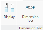
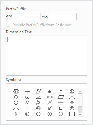
• Dimension Text
Commands in the Dimension Text group allow you to control the display of the dimension text. When you click on the Dimension Text button, the Dimension Text panel appears with options that you can use to control the display of the selected dimension.
◦ Prefix/Suffix — Enables you to specify the prefix and suffix text for the dimension.
◦ Exclude Prefix/Suffix from Basic box — Available only when the tolerance mode for the dimension is set to Basic. Select this option to exclude the prefix and suffix text when available, and display only the dimension text enclosed within the rectangle. When this option is not selected, the dimension text along with the prefix and suffix is enclosed within the rectangle.
◦ Dimension Text — Enables you to modify the dimension text.
◦ Symbols — Enables you to select and insert symbols within the dimension text, or into prefix and suffix text.
With multiple dimensions selected, you can modify the dimension text, and specify the prefix and suffix. All the selected dimensions are updated with the modified dimension text, along with specified prefix and suffix text.
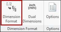
• Dimension Format
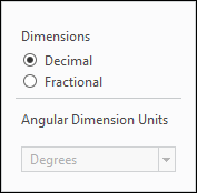
Commands under Dimension Format group allows you to specify the display of dimension in decimal of fractional format, and specify units for the angular dimensions.
You can specify the display format as Decimal or Fractional for the selected linear or radial dimension.
Angular Dimension Units — Enables you to specify units for the selected angular dimension as, Degrees, Degrees, Min., or Degrees, Min., Sec.
When you select multiple dimensions, the format that you select is applied to all the selected dimension. Same is true for units for multiple angular dimensions that you select.
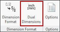
• Dual Dimensions
Commands in the Dual Dimensions group allows you to control the display and precision of the dual dimensions.
◦ Dual Dimensions — Enables you to specify the display, order, and the vertical orientation of the selected dual dimension. You can select the Below option to display the primary and secondary dimensions stacked, or select To Right option to display them in-line.
◦ Precision — Enables you to specify precision of the display of secondary dimension and its related tolerance.
| As tolerance value is not applicable for a reference dimension, the Precision option is disabled for reference dimension and ordinate reference dimensions. |
When you select multiple dimensions, options of the Dual Dimension group are enabled, and appear with no option selected. The options you select, is applied to all the selected dimensions.
• Options
Commands in the Options group allows you to control the position of the model driven dimensions shown in the drawing.
◦ Dependencies — This option is enabled only in Drawing mode. This option allows you to control the position of the model driven dimension shown in drawing.
▪ Placement Position — You can set the placement position of the selected dimension as Driven by model.
▪ Attachment — You can set the attachment point of the selected dimension as References driven by model or Attach point(s) driven by model.
◦ Designation — This option is disabled in Drawing mode. This option allows you to designate annotation elements as control characteristics.
▪ Designate — Select Control Characteristics to designate the annotation elements of the selected dimension as control characteristics. You can use these control characteristics like, the model items, the design intent an critical product information required for manufacturing. You can find and reuse these control characteristics without actually opening the model in Creo.