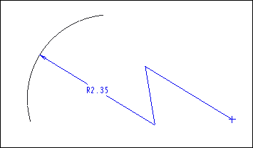
About Z-radius Dimensions
You can create a Z-radius dimension to indicate the location of the center of the arc with a large radius, when you are restricted by the size of the drawing. The dimension line appears folded at two points for a Z-radius dimension. That is, a Z-type jog is automatically added to the dimension line.
|
|
 You can create a Z-radius dimension only in a 2D drawing. |
You must select a true arc of a valid entity to create a Z-radius dimension. The valid entities are draft arcs, circular model edges, circular model sketches and curves, circular silhouette edges, and edges created using cross-sections.
The value of the Z-radius dimension is the radius of the selected arc. You can move the interior z-points of the dimension to change the appearance of the dimension if required. The dimension text is located at the center of the first segment. To modify the placement of the dimension text, set the text_orientation Detail option.
A termination symbol represents the imaginary center of the selected true arc. The symbol appears as a filled dot or a cross symbol. You can select the imaginary center as a reference when you create other dimensions. The dimension value is calculated from the actual center of the arc.
