About Displaying Threaded Components of an Assembly in a Drawing
You can display tapered threaded shafts and holes of an assembly in a drawing in the standard and cross-section views according to the JIS, ANSI, and ISO standards. To display such shafts and holes, use the thread_standards Detail option in conjunction with the hlr_for_threads configuration option.
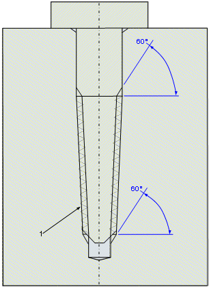
The following figure is a simplified representation of an assembly with a tapered threaded shaft and a hole overlaid on a detailed model:
1. If aligned, the major and minor bolt diameters override the hole diameter