1. Click Framework >  New Connector Element. The New Component dialog box opens.
New Connector Element. The New Component dialog box opens. New Connector Element. The New Component dialog box opens. to access the library and select a non-standard connection from the STEEL CONSTRUCTION INCH > AISC folder. The element appears in the preview area.
Type | Preview | Surfaces | Options | Values |
SINGLE SHEAR PLATE | 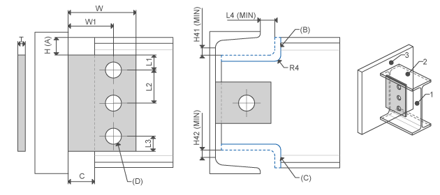 | Profile side face Profile top Attach face | Offset from top Top beam end cope Bottom beam end cope Profile holes | L1, L2, L3 W, W1 C, H L4_MIN H41_MIN H42_MIN R4 |
SHEAR ENDPLATE | 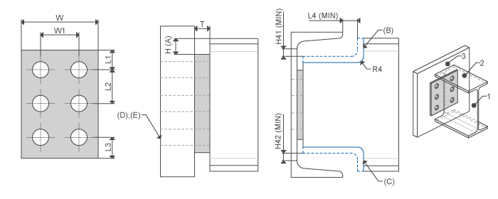 | I-Profile end Attach face | Offset from top Top beam end cope Bottom beam end cope Attach holes thru next Attach holes thru all | L1, L2, L3 W, W1 H L4_MIN H41_MIN H42_MIN R4 |
DOUBLE ANGLES | 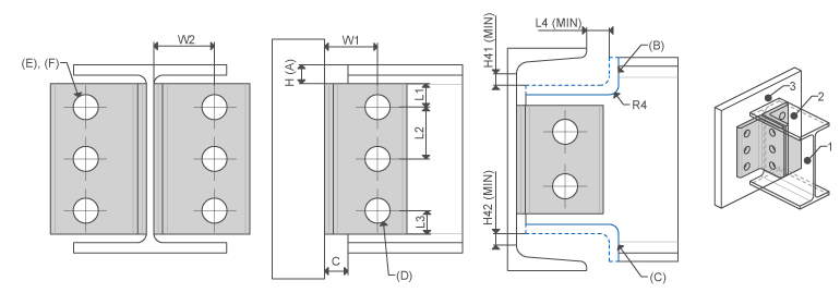 | Profile side face Profile top Attach face | Offset from top Top beam end cope Bottom beam end cope Profile holes Attach holes thru next Attach holes thru all | L1 L2 L3 W W1 C H L4_MIN H41_MIN H42_MIN R4 |
SINGLE ANGLES |  | Profile side face Profile top Attach face | Offset from top Top beam end cope Bottom beam end cope Profile holes Attach holes thru next Attach holes thru all | L1 L2 L3 W W1 C H L4_MIN H41_MIN H42_MIN R4 |