Example: Creating a Non Standard Steel Connection
Consult the table below for a graphic representation of the types of steel connection you can create. Use it to determine which surfaces and check boxes to select and which values to enter during the connection definition process.
1. Click
Framework >
 New Connector Element
. The
New Component dialog box opens.
2. If a connection has not been selected, click

to access the library and select a non-standard connection from either the
STEEL CONSTRUCTION MM > NO STANDARD or the
STEEL CONSTRUCTION INCH > NO STANDARD folders. The element appears in the preview area.
3. Click Next. The Element Definition dialog box opens. The reference collector for the first required surface is active.
4. Select the surface as indicated in the preview.
5. Repeat step 5 to select all required references.
6. If a selected surface is not planar, make sure that the Orient plane reference collector in the Optional References area is active and then select the orientation plane.
7. Click the Settings tab.
8. Select additional element sizes, such as angles, screws, or holes from the appropriate tables.
9. Select or clear check boxes in the Options area.
10. Enter offset values and dimensions.
11. Click Preview to create the connection as a preview, click OK to create the connection using your definition or click Cancel to cancel.
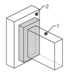
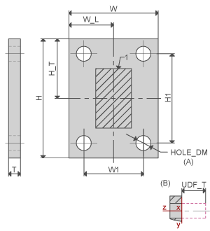
Type | Preview | Surfaces | Values |
ENDPLATE | | Profile top Attach face | H,H_T,H1 W,W_L,W1 T No. of point rows No. of point columns, HOLE DM, UDF_T |
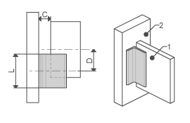
1 ANGLE | | Profile side Attach face | L C D |
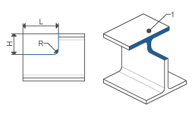
PROFILE END CUTOUT | | Cut surface Attach face | L H R |
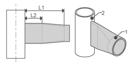
PIPE SQUASH | | Pipe end Cylinder surface | L1, L2 |