ISO and ASME Standard Surface Finish Symbols
Creo provides a set of standard Surface Finish symbols that you can use in addition to the symbols that you define. The surface finish gallery contains the symbols that are in close compliance with the ISO and ASME standards, they include:
• For the ASME standard—ASME Y14-36 2018 Surface Finish symbol.
• For the ISO standard:
◦ ISO_1302_2002 Surface Finish symbol—This symbol is created as per the ISO 1302:2002 standard guidelines and is easy to use.
◦ ISO 21920:2021 Surface Finish symbol—This symbol is created as per the ISO 21920:2021 standard guidelines.
◦ ISO_25178_2016_areal Surface Finish Symbol—This symbol is created as per the ISO 25178-2016 standard guidelines. You can modify Grouping and Variable Text to control the spacing and appearance of values on the symbol instance.
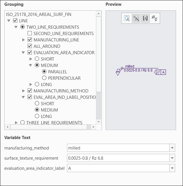
Grouping options available for ISO_25178_2016_areal Surface Finish Symbol are:
• LINE—Control the display of requirement values on the surface finish symbol instance. Select or clear the grouping options to define the number of surface texture requirement lines, position of the requirement values, and position of labels for the graphical display. The following grouping options are available for LINE:
◦ TWO_LINE_REQUIREMENTS—Select to display the surface texture requirement value on two lines in the graphics window. When you select TWO_LINE_REQUIREMENTS, the following grouping options are available:
▪ SECOND_LINE_REQUIREMENTS—Add a second line on the symbol instance for the surface texture requirement value.
▪ MANUFACTURING_LINE—Select the length of the manufacturing line displayed on the surface finish symbol instance.
▪ ALL_AROUND—Select to apply the requirement values all around the selected surface or body.
▪ EVALUATION_AREA_INDICATOR—Adjust the position of the surface texture requirement value in the graphics window. Select SHORT, MEDIUM, or LONG, depending on the length of the surface texture requirement value. For example, if the requirement value is short, then select SHORT; if the requirement value is very long, then select LONG.
▪ MANUFACTURING_METHOD—Select the manufacturing method from the list or enter a new manufacturing method. The following grouping options are available for MANUFACTURING_METHOD:
▪ INDICATED—Select to display the manufacturing method for the surface finish instance.
▪ NOT_INDICATED—Select if there is no manufacturing method for the surface finish instance.
▪ INDICATED_LONG—Select if the value of the indicated manufacturing method is long.
Based on the selection of the manufacturing method, additional grouping options are available. These grouping options are the same for INDICATED, NOT_INDICATED, and INDICATED_LONG. The additional grouping options are:
▪ LAY_AND_ORIENTATION—Select the orientation of lay.
▪ SURFACE_LAY_INDICATOR—Select the orientation of the surface lay indicator on the symbol instance.
▪ SURFACE_LAY_INDICATOR_LABEL—Select to display the surface lay indicator label on the symbol instance.
▪ EVAL_AREA_IND_LABEL_POSITION—Specify the position of the label for the evaluation area indicator. The option selected for the label position should be same as the selection made for the EVALUATION_AREA_INDICATOR. For example, if the EVALUATION_AREA_INDICATOR is selected as LONG, then EVAL_AREA_IND_LABEL_POSITION should also be selected as LONG, same for SHORT or MEDIUM.
◦ THREE_LINE_REQUIREMENTS—Select to display the surface texture requirement value on three lines in the graphics window. The grouping options available for the THREE_LINE_REQUIREMENTS are same as those for TWO_LINE_REQUIREMENTS.
• MATERIAL—Specify if the material is removed for the surface.
• MACHINING_ALLOWANCE—Enter a numeric value for the machining allowance.
• LEADER_LINE—Display the leader line on the symbol instance.