To Create Multiple Holes Using Sketched Entities as Placement References
You can create multiple holes in one Hole feature by using combinations of sketched datum points, and endpoints and midpoints of sketched straight lines.
The points must be created using the  Point tool in the Datum group of the Sketch tab. Construction points cannot be used as references. The lines must be created using the tools that create straight lines in the Sketching group on the Sketch tab. Splines and other non-linear entities, and construction lines, cannot be used as references.
Point tool in the Datum group of the Sketch tab. Construction points cannot be used as references. The lines must be created using the tools that create straight lines in the Sketching group on the Sketch tab. Splines and other non-linear entities, and construction lines, cannot be used as references.1. Perform one of the following actions:
◦ Open the Hole tab first:
1. Click >  Hole. The Hole tab opens.
Hole. The Hole tab opens.2. Click the Placement tab.
3. Under Type, select Sketched. The Sketch collector is active.
4. To sketch or select the placement sketch, do one of the following:
▪ To select the sketch, click the Sketch collector, and select a sketch that contains sketched datum points, sketched straight lines, or both.
▪ To sketch the sketch:
1. Click Define. The Sketch dialog box opens.
2. Set the sketch plane and orientation, and then click Sketch. The Sketch tab opens.
3. Sketch datum points, straight lines, or both.
4. Click  OK to close the Sketch tab.
OK to close the Sketch tab.◦ Select an existing sketch first:
1. Select a sketch that contains sketched datum points, sketched straight lines, or both.
2. Click > Hole. The Hole tab opens. On the Placement tab, the Type is Sketched, and the selected sketch appears in the Sketch collector.
Hole. The Hole tab opens. On the Placement tab, the Type is Sketched, and the selected sketch appears in the Sketch collector.2. Select the sketched datum points and straight lines to use as references on which to place holes.
3. To define the types of sketched entities to use as placement references, under Sketch, select any combination of the following items:
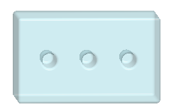
◦  Points—Places holes on sketched datum points.
Points—Places holes on sketched datum points.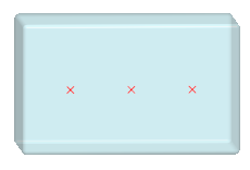
◦  Midpoints—Places holes on midpoints of sketched straight lines. The midpoints are determined automatically.
Midpoints—Places holes on midpoints of sketched straight lines. The midpoints are determined automatically.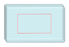
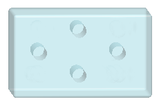
◦  Endpoints—Places holes on endpoints of sketched straight lines. The endpoints are determined automatically.
Endpoints—Places holes on endpoints of sketched straight lines. The endpoints are determined automatically.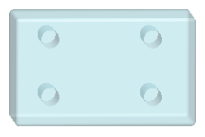
4. Define other hole settings.
5. Click  OK.
OK.
OK.You can use an edge, surface, or axis of one of the holes in the hole feature that was created using sketched placement to add a reference pattern that will be applied to all the holes in the feature.