Hole Placement Types
You can select the hole placement type that defines the way in which the hole is placed. You can select a placement type in the following ways:
• On the Placement tab, select a placement type from the Type list
• Place your pointer over a secondary placement handle, and right-click and choose a placement type from the shortcut menu
The following hole placement types are available:
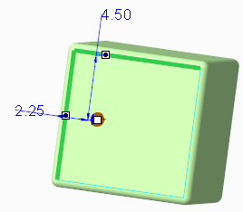
•  Linear
Linear◦ Places the hole on a surface by using two linear dimensions
◦ Available when you select a datum plane, or a planar, cylindrical, or conical solid surface as the primary placement reference
◦ This type is selected by default when you select a surface or datum plane as the primary placement reference
• Linear referencing an axis
◦ Places the hole by referencing a datum axis or by referencing the axis of another hole located on the same surface
◦ The axis should be normal to the primary placement reference of the newly created hole
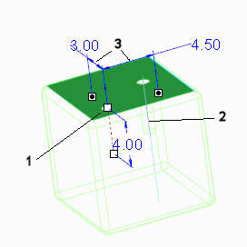
1. Newly created hole
2. Axis is secondary reference
3. Orthogonal dimension
•  Radial
Radial◦ Places the hole by using a linear and an angular dimension
◦ Available when you select a datum plane, or a planar, cylindrical, or conical solid surface as the primary placement reference
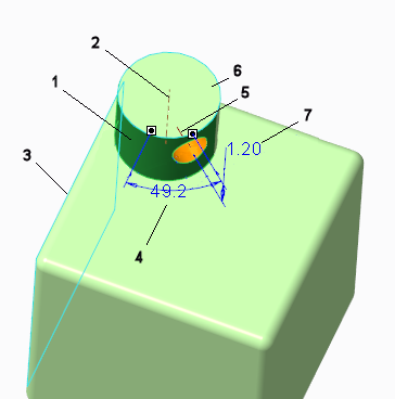
1. Cylinder surface is placement reference
2. Cylinder axis
3. Side surface of cube is planar reference
4. Angle is measured from plane that passes through the cylinder axis and that is parallel to the planar reference
5. Axis of hole
6. Top surface of cylinder is reference
7. Axial distance measured from top surface to hole axis
•  Diameter
Diameter◦ Places the hole by rotating the hole around a diameter reference
◦ Uses an axis in addition to linear and angular dimensions
◦ Available when you select a planar solid surface or a datum plane as the primary placement reference
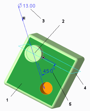
1. Surface is the placement reference
2. Axis is the reference for the diameter and for the angle
3. Diameter measurement determines the distance of the new hole from the axis reference
4. Datum plane is the reference for the angle
5. Angle is measured by rotating the datum plane around the axis
•  Coaxial
Coaxial◦ Places the hole at the intersection of an axis and a surface
◦ The axis does not have to be perpendicular to the surface
◦ Available when you select a surface, datum plane, or axis as the primary placement reference
◦ When the primary placement reference is an axis, Coaxial becomes the only placement type available, and this type is selected by default
Coaxial becomes the only placement type available, and this type is selected by default◦ Secondary placement reference handles and the Coaxial shortcut menu command are not available when using this placement type
Coaxial shortcut menu command are not available when using this placement type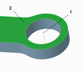
1. Datum axis
2. Surface
•  On Point
On Point◦ Aligns the hole to a datum point
◦ The datum point does not have to be on the surface
◦ Available only when you select a datum point as the primary placement reference
◦ When the primary placement reference is a datum point, On Point becomes the only placement type available, and this type is selected by default
On Point becomes the only placement type available, and this type is selected by default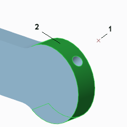
1. Datum point
2. Surface
•  Sketched
Sketched◦ Places multiple holes within a single Hole feature.
◦ Places holes on any combination of sketched datum points, and endpoints and midpoints of sketched straight lines. The endpoints and midpoints are determined automatically.
◦ Available when you select a sketch as a placement reference.
Sketch:
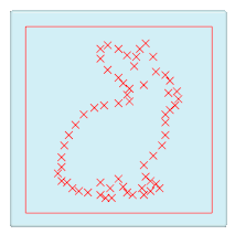
Holes from points:
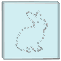
Holes from points and endpoints:
Holes from points, endpoints, and midpoints:
You cannot switch between the Sketched placement type and any other placement type when these conditions apply: • When copying a hole feature using partially dependent copy, or redefining a partially dependent copied hole feature, in any hole type except a  Simple hole with a Flat profile type Simple hole with a Flat profile type• When redefining the source hole feature, that was used to create a partially dependent copied hole feature or a partially dependent mirrored hole feature |