To Create a Simple Coaxial Hole
1. Click >  Hole. The Hole tab opens.
Hole. The Hole tab opens.2. Select an axis on the model. This is your primary placement reference for the coaxial hole. The Coaxial placement type is selected on the Placement tab. The hole preview geometry is aligned to the selected axis.
3. Hold down the CTRL key to select another placement reference.
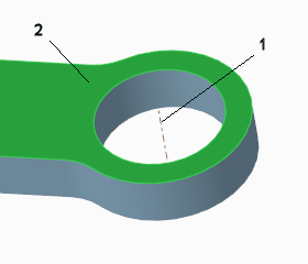
1. Datum axis
2. Surface
4. To set the hole diameter, perform any of these actions:
◦ Double-click the  diameter value in the graphics window, type a value, and press ENTER.
diameter value in the graphics window, type a value, and press ENTER.◦ Type a value in the Diameter box and press ENTER.
Diameter box and press ENTER.5. To set the hole depth, select a depth option, and if needed depending on the option, type a depth value in the box or select a reference.
6. To ensure that the entire top of the hole intersects the outside of the solid geometry, on the Shape tab, make sure that the Top Clearance check box is selected.
7. To select the bodies from which geometry is removed, click the Body Options tab and select an option:
◦ To cut geometry from all the bodies that the feature passes through, select All.
◦ To cut geometry from selected bodies:
1. Select Selected.
2. Click the body collector, and then select bodies from which to cut geometry.
8. Click  OK.
OK.
OK.