To Create Beam-based Lattice
When you create beam-based lattice, you choose a three-dimensional cell shape, and a configuration of beams inside the lattice cell.
Stochastic lattice, a type of beam-based lattice, is described in a separate topic listed under the Related Links.
1. Click >  Lattice. The Lattice tab opens.
Lattice. The Lattice tab opens.2. Next to Lattice type, select Beams, and define the following:
a. To define the direction with which the z-axis of the cell is aligned, select Z, X, or Y.
b. To define how the lattice cells are propagated in the internal volumes, from the  propagation list, select one of the following:
propagation list, select one of the following:▪ To add lattice cells one after the other in straight lines and layers, click Regular.
▪ To add lattice cells in a circular pattern, click Quasi-radial, and type a value for Base cell number.
▪ To add lattice cells in herringbone structure, click Herringbone. Herringbone propagation requires a non-zero skew angle.
c. To set the scale of the lattice, type the value in the scale box  and press Enter. This value is relative to the current size of the cell.
and press Enter. This value is relative to the current size of the cell.d. To define the lattice representation, in the representation list  , select an option:
, select an option:▪ Full geometry—Full geometry representation requires more resources and might cause the system to be slow, particularly when the lattice contains a large number of lattice cells.
▪ Simplified
▪ Homogenized—Creates a special quilt with semi-transparent surfaces to represent the lattice volume. It defines the lattice without actually creating it in the model. The mathematical definition of the lattice is stored with the model. This representation is particularly useful if you plan to perform structural linear static or modal analyses in Creo Simulate. Homogenized representation is specially used for dense lattice structures, as it considerably reduces model size and analysis run time.
Not homogenized: 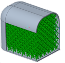 | Homogenized: 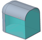 |
4. For lattice that does not replace a body, you can define the body to which the feature is added. Click the Body Options tab, and perform one of the following actions:
◦ To add geometry to an existing body, click the body collector, and then select the body to which geometry is added.
◦ To create the feature in a new body, select the Create new body check box. The name of the new body appears in the body collector.
5. Click the Cell Type tab, and define the cell shape and size:
a. Next to Cell shape, select  Triangular,
  Square,
  Hexagonal, or
  Octagonal.
Triangular, Square, Hexagonal, or Octagonal.b. To set the dimensions of the cell, under Cell size, type the values of the X, Y, and Z dimensions of the cell, in the model units.
c. To set the slanting angle of the cell, next to Skewing angle, type a value.
6. Click the Cell Fill tab, and define the lattice beams:
a. To set the internal structure of the cell, next to Cell configuration, select an option, and then choose beam types:
▪ Custom
▪ Inner horizontal beams
▪ Inner vertical beams
Inner horizontal beams and inner vertical beams used together
▪ Outer horizontal beams
▪ Outer vertical beams
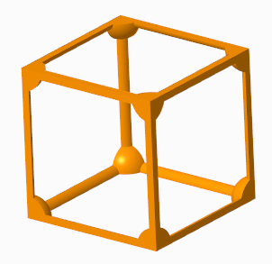
Outer horizontal beams and outer vertical beams used together
▪ Angular beams
▪ Outer truss beams
▪ Inner truss beams
▪ Clear all
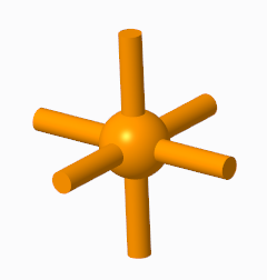
▪ Star
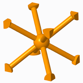
The Star configuration uses only Angular beams.
▪ Truss
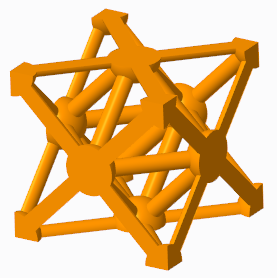
The Truss configuration uses only Outer truss beams and Inner truss beams. Available for Square and Triangular cell shapes.
b. To remove beams that are not attached to a solid or another beam on both ends in beam-based lattice, select the Remove dangling beams check box.
c. When Straight profile is selected, to add balls at the corners where the beams intersect and in the center of the cell, select the Ball diameter check box, and then type a value to define their sizes.
d. To create rounds at the concave edges between the lattice balls and beams, select the Round radius check box, and type the radius value. The round radius is ignored when you create lattice with varied density. Available for Full geometry representation.
e. To define the shape of the beam cross section, next to Cross section type, select a shape.
f. To define the size of the beam cross section, next to Cross section size, type a value.
g. To define the shape of the beam, next to Profile type, select a shape:
▪ Straight
▪ Parabolic, and then type values to define these parameters:
▪ Parabolic radius
▪ Profile coefficient
7. To create lattice with varied density, see the topic To Create Lattice with Varied Density.
8. To add transition beams between the lattice and the internal horizontal walls (ceiling) of the bounded lattice volume, see To Define Lattice Transitions.
9. Click  OK.
OK.
OK.