About the Lattice Feature User Interface
The Lattice tab consists of commands, tabs, and shortcut menus. Click > >  Lattice to open the Lattice tab.
Lattice to open the Lattice tab.Commands
• Lattice type
◦ Beams—Creates lattice using 3D cells that contain beams arranged into structures, that are propagated in a pattern.
◦ 2.5D—Creates lattice by projecting a planar shape perpendicular to the plane as the lattice cell, and propagating the cell to fill the defined area.
◦ Formula Driven—Creates lattice using a formula to define the cell shape.
◦ Custom—Creates lattice using a part that you create in Creo Parametric and import into the Lattice feature to define the lattice cell shape.
•  —Defines the cell alignment direction of the z-axis. You can select Z, X, or Y.
—Defines the cell alignment direction of the z-axis. You can select Z, X, or Y.•  —Defines how the cells are positioned in the internal volume for beam-based and 2.5D lattice.
—Defines how the cells are positioned in the internal volume for beam-based and 2.5D lattice.◦ Regular—Fills the volume layer by layer.
◦ Quasi-radial—Fills the volume in a circular pattern.
▪ Base cell number—Sets the number of cells in a single circle.
◦ Herringbone—Fills the volume in zigzag pattern.
•  —Sets the size of the cell relative to its current cell size, keeping its current proportions.
—Sets the size of the cell relative to its current cell size, keeping its current proportions.•  —Defines the lattice representation.
—Defines the lattice representation.◦ Full geometry—Creates full lattice geometry that includes all properties and an accurate appearance.
◦ Simplified—Creates a light-weight approximation of the lattice.
◦ Homogenized—For beams lattice, creates a special quilt to represent the lattice volume, to use for analyses in Creo Simulate.
◦ Voxelized—In formula-driven lattice, creates lattice using voxels.
▪  —Sets the level of accuracy of the voxel representation.
—Sets the level of accuracy of the voxel representation.◦ Custom—Design your own lattice cell in Creo Parametric Part mode, and then import the PRT file into the part model to use as the lattice cell.
▪ Open Cell—Imports the part to use as a cell for a custom designed lattice feature.
Tabs
• Lattice Region
◦ Replace body with lattice check box
▪ When the check box is cleared—Adds lattice inside a volume that you define by selecting bounding surfaces.
The following options are available:
▪ Lattice volume region collector—Displays the surfaces that define the volume of the lattice.
▪ Details—Lists the bounding surfaces sets.
▪ When the check box is selected—Replaces the selected body with lattice.
The following options are available:
▪ Body to replace collector—Displays the body to replace with lattice.
▪ Create shell check box—Includes the shell of the body as a part of the lattice. When this option is selected, the following options become available:
▪ Thickness—Controls the thickness of the shell.
▪ Shell side—Controls the direction in which the shell is created. You can choose Inside or Outside.
▪ Excluded shell surfaces collector—Displays the surfaces that are excluded from the shell.
▪ Details—Displays the relevant surface sets.
◦ Skip failed geometry check box—Does not add lattice elements in places where geometry fails. Not available for formula-driven lattice.
◦ Orientation—Selects a coordinate system or a build direction analysis to define the orientation of the lattice.
◦ First cell position collector—Selects a coordinate system as the location for the first lattice cell. The automatically selected location is the origin of the default coordinate system.
• Cell Type
Use this tab to define the cell parameters.
For beam-based lattice, these options are available:
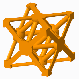
◦ Cell Shape—Defines the shape of the lattice cell.
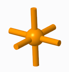
▪  Triangular
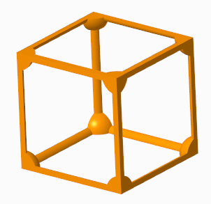
Triangular▪  Square
Square▪  Hexagonal
Hexagonal▪  Octagonal
Octagonal▪  Stochastic—Creates lattice by connecting randomly distributed points with beams inside volumes or over surfaces.
Stochastic—Creates lattice by connecting randomly distributed points with beams inside volumes or over surfaces.◦ Cell size—Defines the X, Y, and Z dimensions of the cell. These are the absolute cell dimensions, using the model units.
◦ Skewing angle—Defines the angle of cell slanting.
For 2.5D lattice, these items are available:
◦ Cell shape—Defines the shape of the lattice cell.
▪ Triangular
Triangular▪ Square
Square▪ Hexagonal
Hexagonal▪  Octagonal
Octagonal◦ Cell size—Defines the X and Y dimensions of the cell. These are the absolute cell dimensions, using the model units.
◦ Skewing angle—Defines the angle of cell slanting.
For formula-driven lattice, these items are available:
◦ Function—Defines the formula that drives the shape of the lattice cell for formula-driven lattice.
◦ Cell size—Defines the X, Y, and Z dimensions of the cell. These are the absolute cell dimensions, using the model units.
For custom lattice, these items are available:
◦  —Imports the part to use as a cell for a custom designed lattice feature.
—Imports the part to use as a cell for a custom designed lattice feature.◦ Cell size—Defines the X, Y, and Z dimensions of the cell. These are the absolute cell dimensions, using the model units.
◦ Fixed scale—Defines the cell scale in relation to its size when you import it for custom lattice.
For stochastic lattice, these items are available:
◦ Algorithm
▪ Delaunay triangulation—Generates the lattice using Delaunay triangulation.
▪ Voronoi diagram—Generates the lattice using Voronoi diagrams.
◦ Stochastic lattice location
▪ Inside volume—Creates lattice in the inside volume of the model.
▪ On bounding surfaces—Creates lattice over the bounding surfaces of the model.
▪ Volume + bounding surfaces—Creates lattice over the bounding surfaces and in the inside volume of the model.
◦ Stochastic cell definition
▪ Cell definition method
▪ Target cell size—Defines the lattice cell size measured diagonally across the bounding box of the cell.
▪ Number of cells—Sets the target number of cells in the lattice structure.
▪ Min. beam length—Sets the minimum length for lattice beams.
▪ Max. beam length—Sets the maximum length for lattice beams.
▪ Randomize—Recalculates the random distribution of the points on which the lattice structure is based.
• Cell Fill
For beam-based lattice, use this tab to define and display the beams:
◦ Cell configuration—Sets the internal structure of the cell.
▪ Custom—Enables you to select combinations. For triangular-, square-, or hexagonal-type lattice, controls the internal structure of the cell by defining which types of beams are included in or excluded from the structure.
▪ Inner horizontal beams
▪ Inner vertical beams
Inner horizontal beams and inner vertical beams used together
▪ Outer horizontal beams
▪ Outer vertical beams
Outer horizontal beams and outer vertical beams used together
▪ Angular beams
▪ Outer truss beams
▪ Inner truss beams
▪ Clear all—Clears all beam types.
▪ Star—Selects only Angular beams.
▪ Truss—Selects only Outer truss beams and Inner truss beams. Available for Square and Triangular cell shapes.
◦ Remove dangling beams—Removes beams that are not attached to a solid or another beam on both ends in beam-based lattice.
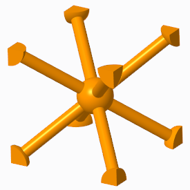
◦ Ball diameter—When Straight profile is selected, you can add balls at the corners where the beams intersect, and in the center of the cell, and set their sizes.
◦ Round radius check box—Creates rounds at the concave edges between the lattice balls and beams, and defines the radius value. The round radius is ignored for lattice with varied density. Available for Full geometry representation.
◦ Cross section type—Defines the shape of the cross section of the beam.
◦ Cross section size—Defines the size of the cross section of the beam.
◦ Profile type—Defines the shape of the beam.
▪ Straight
▪ Parabolic
▪ Parabolic radius—Sets the parabolic radius.
▪ Profile coefficient—Sets the coefficient of the profile.
For 2.5D lattice, these items are available:
◦ Wall thickness—Sets the thickness of the cell walls.
◦ Round radius check box—Creates rounds at the concave edges of the cells, and defines the radius value. Available for Full geometry representation.
◦ Add drain holes—Adds slot-shaped holes to the cells in 2.5D lattice.
▪ Width—Defines the width of the drain hole.
▪ Length—Defines the length of the drain hole.
▪ Spacing—Defines the distance between two drain holes.
For formula-driven lattice, these items are available:
◦ Wall thickness—Sets the thickness of the cell walls.
◦ Remove unattached geometry—Removes geometry that is not attached to a solid.
For stochastic lattice, these items are available:
◦ Cross section size—Defines the size of the cross section of the beam.
◦ Ball diameter—Adds balls where the beams intersect and in the center of the cell, and set their sizes.
◦ Remove dangling beams—Removes beams that are not attached to a solid or another beam on both ends in beam-based lattice.
◦ Trim boundary—Trims the beams at the boundary of the lattice.
• Density
Use this tab to define lattice with varied density for beam-based and formula-driven lattice.
For beam-based lattice, the density is determined by the size of the cross section of the beam. The following items are available:
◦ Variable Beams—Manages the sets. Each set defines a volume region.
◦ Distance—Defines the distance from the reference where the varied lattice is created. This determines the size of the volume region.
◦ Target cross section size—Sets the cross section of the beam at the reference you specified.
◦ Size change rate—Sets how quickly the beam size changes. When this option is set to 1, the rate of change is linear. When the value is smaller than 1, the rate is lower than linear. When the value is greater than 1, the rate is higher than linear.
◦ Cross section cutoff—Defines the cross section size below which lattice is not created.
◦ Continuous variability check box—Sets whether beams can be tapered.
◦ References collector—Defines the references that are used to create the varied density of a volume region. This reference can be a point, a curve, a coordinate system origin, or a surface.
For formula-driven lattice, the following items are available:
◦ Variable Wall Thickness—Manages the sets. Each set defines a volume region.
◦ Distance—Defines the distance from the reference where the varied thickness is created. This determines the size of the volume region.
◦ Target wall thickness—Sets the thickness of the wall at the reference you specified.
◦ Size change rate—Sets how quickly the wall thickness changes. When this option is set to 1, the rate of change is linear. When the value is smaller than 1, the rate is lower than linear. When the value is greater than 1, the rate is higher than linear.
◦ Wall thickness cutoff—Defines the cross section size below which lattice is not created.
◦ References collector—Defines the references that are used to create the varied wall thickness of a volume region. This reference can be a point, a curve, a coordinate system origin, or a surface.
For stochastic lattice, the following items are available:
◦ Adaptive distribution—Manages the sets. Each set defines a volume region.
◦ Distance—Defines the size of the area where the density changes.
◦ Density ratio—Sets the density at the selected reference.
◦ Density change rate—Sets the rate of change of the density.
• Transition
Transitions improve the printability of a model that contains a beam-based lattice structure, by adding transition beams between the lattice and the internal horizontal walls (ceiling) of the bounded lattice volume.
◦ Transition type
▪ None—Does not create transition beams.
▪ Vertical—Creates transition beams that contain an elbow, so that the transition beams are vertical at the supported point in the model wall.
▪ Slanted—Creates transition beams that slant from an elbow in the lattice to the supported point in the model wall.
◦ Critical angle—Defines the critical angle for the walls of the internal bounded volume of the lattice structure. Additional transition beams are added between the lattice and the supported wall in areas where the angle between the normal to the surface and the build direction is below the critical angle.
◦ Max. unsupported distance—Defines the distance on the wall that can be 3D printed without the additional support of transition beams.
◦ Targeted min. beam length—Defines the minimum length of the transition beams, or of the beams of the original lattice that are split due to transition beam creation.
◦ Max. beam length—Defines the maximum length of the transition beams.
◦ Targeted min. angle between beams—Defines the minimal allowed angle between transition beams that share a common junction.
◦ Distance to elbow—For vertical transition beams without tapered ends, defines the distance from the supported point in the model wall to the elbow in the transition beam that connects to the transition beam structure.
◦ Taper end of beams check box—For vertical transition beams, covers the ceiling area with support by tapering the transition beams in the layer closest to the ceiling.
• Body Options
Not available when Replace body with lattice is selected. Not available for creating assembly-level features.
◦ Add geometry to body
▪ Create new body check box—Creates the feature in a new body.
▪ Body collector
▪ Selects the body to which geometry is added when you add the feature to an existing body. Geometry is added to the default body, unless you select a different body.
▪ Shows the name of the new body when you create the feature in a new body.
• Properties
Name—Defines the name of the lattice feature.