Defining a Part Loop
If the stackup is defined between features on two different parts, the Assembly area opens in the New Stackup dialog box.
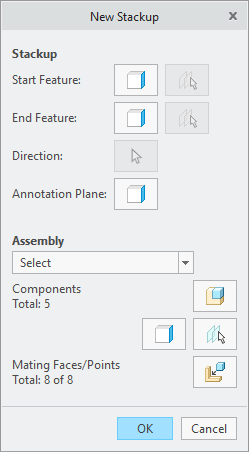
Define the parts involved in the stackup loop and the surfaces that control the parts, commonly referred to as assembly constraint surfaces. When the path is found between the two surfaces through the assembly constraints in the model, the part loop is defined automatically. If the path is not found, you must define the loop manually. When the automatic method is selected, a list of different paths that are found is displayed. Select a path to highlight the parts in the loop in the graphics window to verify and select.