Fluid Domain Extraction
The first step in the Flow Analysis simulation process is the extraction of the fluid domain from an existing CAD model. Click
 Flow Analysis
 >
 Create Fluid Domain
 to create a fluid domain. The
Fluid Domain Creation tab opens.
The details in fluid volume extraction are listed below:
• Openings tab—Contains the surfaces and faces that are automatically recognized from the CAD surfaces. For details about the surfaces, click a surface and view the surfaces that appear in the Surface Sets dialog box. To remove existing holes from the domain, right-click the hole and select Remove.
• Seed Surfaces tab—Contains the surfaces and faces that correspond to specific cavities of interest. This allows you to filter out and select additional cavities that are detected from the screw holes, and indents on the exterior of the model. The selected surfaces appear in the Faces box. The Select all voids allows you to automatically select seed surfaces in a fully enclosed model without openings.
Without Seed Surfaces | With Seed Surfaces |
| |
• Domain—For the fluid domain, select Internal from the list.
• Add to Simulation—Automatically adds the extracted domain as a fluid domain for the simulation.
• Shrinkwrap—Merge components during the fluid domain extraction. In some cases, if the normal merge approach fails to create the fluid domain, you can use the shrinkwrap option.
• 
—Preview or Regenerate fluid domain
• 
—Apply the selected extraction
• 
—Exit
Fluid domains appear under Domains in the Flow Analysis Tree.
Checking for Leaks in the Model
Internal flow simulations require watertight geometry to provide accurate results. When you create a fluid domain in Creo Flow Analysis, the merged assembly should have no gaps or openings. Check leaks and Shortest Path allow you to locate such gaps in the assembly.
To use the Check leaks button, follow the steps listed below:
1. In the Openings tab, Faces box, select all surfaces that contain a minimum of one opening.
2. Click the Check leaks button to activate the Check leaks display.
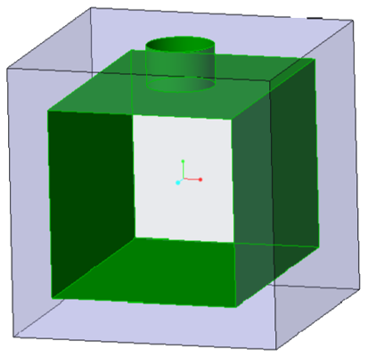
a. Models without leaks—Exterior surfaces are translucent. Interior surfaces corresponding to the fluid domain become green.
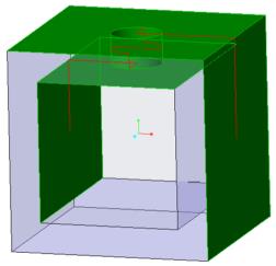
b. Models with leaks—All surfaces are green.
Example of a model without leaks – All three surfaces with openings are selected as faces and appear in the Faces box | Example of a model with leaks – The top surface with the circular opening is not selected as a face and does not appear in the Faces box |
| |
3. Move the slider to view green surfaces of the model in the sequence they are detected. Identify locations where the detected surfaces transition from internal surfaces to external surfaces.
Using the Check leaks tool – In the example, the top surface with the circle, which is not selected, is the first exterior surface to turn green indicating where the leak originates |
|
To use the Shortest Path button, follow the steps listed below:
Example of an internal and external surface selected | Example of a model with leaks – The top surface with the circular opening was not selected in the image to the left. A red line passes from the selected internal surface, through the unselected opening in the model, and connects to the selected external surface |
| |
1. In the Openings tab, Faces box, select all surfaces that contain a minimum of one opening.
2. Click the Shortest Path button to toggle the Shortest Path tool display. The merged assembly appears translucent. The Surface Sets dialog box opens.
3. Select one internal surface that corresponds to the fluid domain and one external surface of the model.
4. Click OK.
a. Models without leaks—A dialog box appears with the message that there are no leaks.
b. Models with leaks—A red line connects the internal and external surfaces that you selected. The line passes through any unselected openings or gaps in the model.
5. Click the Shortest Path button to exit the Shortest Path button.
Splitting Domains
Select a domain and then in the
Simulation Domains group click
 Split Domain
 to split an extracted fluid domain.
A fluid domain is split for the following reasons:
• To separate a rotating or moving volume from a stationary volume.
• To separate two stationary or rotating volumes.
Planar or cylindrical splits are performed on the extracted domain.
To split the domain, follow the steps listed below:
1. In the Model Tree select the extracted domain.
2. Select the Split type as Plane or Cylinder:
◦ Plane—Specify the plane for the split and set the Offset value.
◦ Cylinder—Specify the plane for the split, and set Center point and Radius. Select Default or Custom for the coordinate system. When you select Custom, the Coordinate System dialog box opens where you specify the reference coordinate system.
3. Click

to change the side that appears for the split operation.
4. Click
. The split domains appear in the
Model Tree.